Winco ASCO 300 Accessory 72A Serial Module User Manual
Installation manual
381333–240 C
50 Hanover Road, Florham Park, New Jersey 07932–1591 USA
For sales or service call 1 800 800–2726 (ASCO) www.ascopower.com
ASCO POWER TECHNOLOGIES CANADA PO Box 1238, 17 Airport Road, Brantford, Ontario, Canada N3T 5T3
telephone 519 758–8450, fax 519 758–0876, for service call 1 888 234–2726 (ASCO) www.asco.ca
Installation
Manual
Catalog 5110
Accessory 72A Serial Module
for 4000 Series, 7000 Series, & Series 300 ATSs
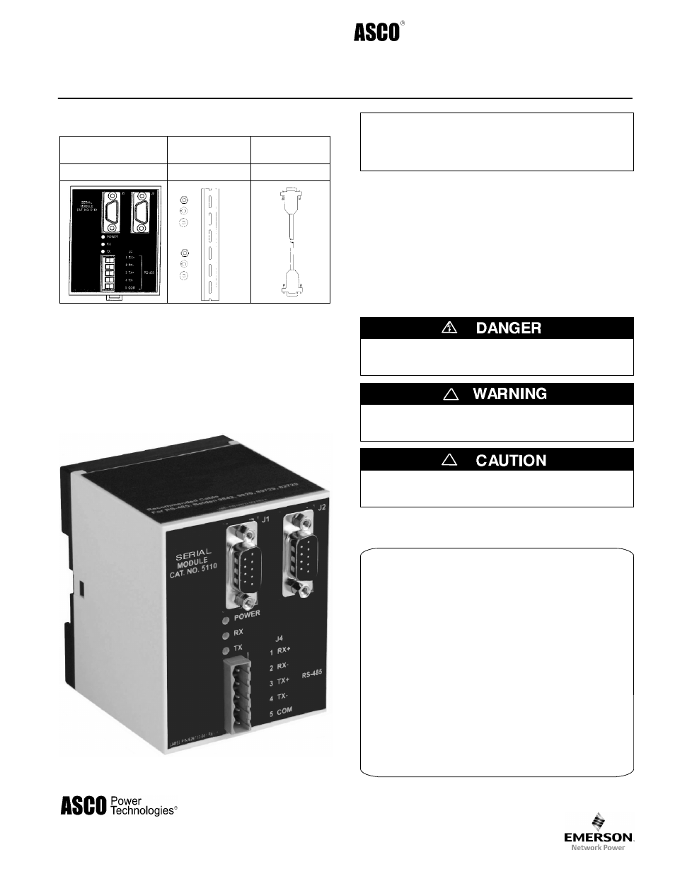
Contents of Accessory 72A Kit 755257
Serial Module
DIN Rail &
Hardware
10–inch
Serial Cable
629750
754607
629798–001
Accessory 72A Kit 755257–001
Includes the above three items plus a 4–foot serial cable
( 629798–002 ) for a Power Manager.
For G–design 7ATB, 7ACTB, and 7ADTB Automatic
Transfer & Bypass–Isolation Switches a 9–foot serial cable
( 629798–004 ) must be ordered separately.
Refer to the wiring diagrams and drawings
provided with the automatic transfer switch (ATS).
The ASCO Catalog 5110 Serial Module (optional Accessory
72A) is required with 4000 Series, 7000 Series, or Series 300
Automatic Transfer Switches (ATSs) for serial communica-
tions. With this option installed, the ATS Controller can
respond to requests (from ASCO devices) to send the status
of standard features and optional accessories. In addition, the
controller can receive remote commands to control the
operation of the ATS.
This manual explains how to install the Serial Module on
4000 Series, 7000 Series, and Series 300 ATSs only.
DANGER is used in this manual to warn of high
voltages capable of causing shock, burns, or death.
WARNING is used in this manual to warn
of possible personal injury.
!
CAUTION is used in this manual to warn
of possible equipment damage.
!
An experienced licensed electrician should install the Serial
Module.
TABLE OF CONTENTS
page
INSTALLATION
Installation Drawing
786556
. . . . . . . . . . . . . . . . .
Mounting
1
. . . . . . . . . . . . . . . . . . . . . . . . . . . . . . .
Connections
1
. . . . . . . . . . . . . . . . . . . . . . . . . . . .
Setting the ATS Address
3
. . . . . . . . . . . . . . . . . .
Address Form
5
. . . . . . . . . . . . . . . . . . . . . . . . . . .