Serial module installation – Winco ASCO 300 Accessory 72A Serial Module User Manual
Page 3
SERIAL MODULE INSTALLATION
1
With Accessory 72A Serial Module Catalog 5110 added
to 4000 Series, 7000 Series, and Series 300 Automatic
Transfer Switches (ATSs), real–time data can be accessed
through the serial interface. Refer to the installation
drawings provided and follow the steps below to install
the Serial Module.
De–energize the Normal and Emergency sources
before opening the enclosure. Place the engine
generator starting control in the OFF position.
Make sure the generator is not operating.
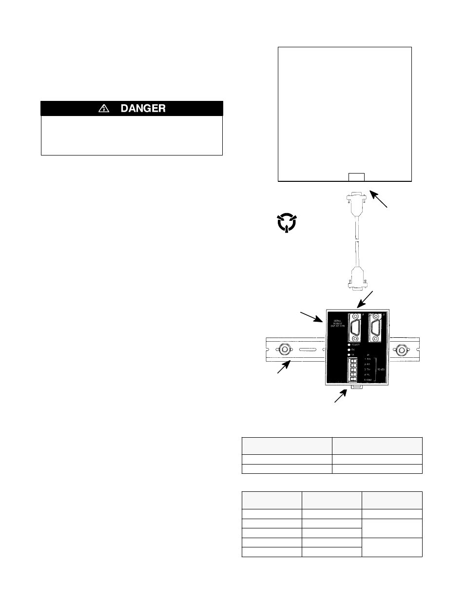
Mounting
The Serial Module mounts on a DIN rail directly under
the ATS controller. See Figure 1 and Figure 2.
1. De–energize both Normal and Emergency sources that
feed the ATS. Then open the enclosure door and check
with a non–contact AC voltage detector.
2. Mount the DIN rail (supplied in the kit) onto two studs
(on the door) below the controller.
3. Install the Serial Module onto the DIN rail by hooking
the top of the module on the top of the DIN rail and
rocking it downward until it snaps in place. If you need
to remove the Serial Module, pull the release tab
underneath.
Connections
A short serial cable connects the Serial Communication
Module to the Controller. If a Power Manager is present,
a long serial cable connects the Serial Communication
Module to the Power Manager. Refer to the wiring
diagram provided. The wiring must be performed by an
experienced licensed electrician in accordance with the
National Electrical Code and all local codes.
1. Install the 10–inch serial cable (from the kit) between
the ATS controller receptacle (J7 on 4000 & 7000
Series, J4 on Series 300) and the Serial Module
receptacle J1.
2. If a Power Manager is present, connect the 4–foot
serial cable between the Power Manager receptacle J5
and the Serial Module receptacle J2.* See Figure 2.
* A 9–foot serial cable (629798–004) is required
for G7ATB, G7ACTB, G7ADTB.
3. Prepare and connect the specified communication
cable (Table A) to the Serial Module J4 terminal plug
as listed in Table B and shown in Figure 3.
4. When daisy chaining multiple ATSs, the ATS that is the
farthest distance
from the controlling device must have
a termination resistor. The Serial Module has a
built–in termination resistor that can be connected by
moving two DIP switches to ON. See Figure 4.
serial
connector
Serial
Module
DIN rail
serial
connector
J1
Group 1 or 5
ATS Controller
9–pin D
connector
Touch ground first !
Electrostatic
sensitive devices.
10–inch
serial cable
removable plug
with terminals
Figure 1. Serial Module mounted on DIN rail.
Table A. Acceptable Communication Cable.
Standard 80 degree C
Cable
Plenum Rated
Cable
Belden 9842 or 9829
Belden 89729 or 82729
Alpha 6202C or 6222C
Alpha 58902
Table B. Serial communication connections.
Serial Module
J4 terminals
Function
Description
5
COM
shield
3
TX+
twisted pair
4
TX–
twisted pair
1
RX+
twisted pair
2
RX–
twisted pair