Installation – Winco ASCO 300 J Design 600 Amp User Manual
Page 8
INSTALLATION
(continued)
1---4
Figure 1-4. Maintenance handle operation and contact position indicators.
observe these lights
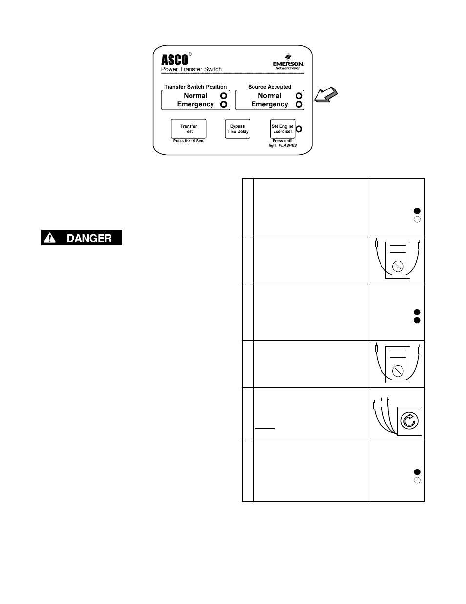
Figure 1–5. Standard controls and indicators.
2 – Voltage Checks
First check nameplate on transfer switch; rated voltage
must be the same as normal and emergency line
voltages.
Use extreme caution when using a meter to
measure voltages in the following steps.
Do not touch power terminals; shock, burns, or
death could result !
Perform steps 1 through 6 at the right. Observe the
status lights. See Figure 1–5.
O
Black circle means light is on.
P
White circle means light is off.
* If necessary, adjust voltage regulator on the
generator according to the manufacturer’s recommen-
dations. The Automatic Transfer Switch will respond
only to the rated voltage specified on the Transfer
Switch nameplate.
1
Close the normal source circuit
breaker. The
Normal Transfer
Switch Position and the Normal
Source Accepted lights should
come on.
Source Accepted
Normal
Emergency
2
Use an accurate voltmeter to
check phase to phase and
phase to neutral voltages pres-
ent at the transfer switch normal
source terminals.
3
Close the emergency source
circuit breaker. (Start generator,
if necessary.) The
Emergency
Source Accepted light should
come on.
Source Accepted
Normal
Emergency
4
Use an accurate voltmeter to
check phase to phase and
phase to neutral voltages pres-
ent at the transfer switch emer-
gency source terminals.*
5
Use a phase rotation meter to
check phase rotation of emer-
gency source; it must be the
same as the normal source.
A B C
6
Shut down the engine–genera-
tor, if applicable. The
Emergen-
cy Source Accepted light should
go off. Then put the starting
control selector switch (on the
generator set) in the
automatic
position. Close enclosure door.
Source Accepted
Normal
Emergency
Now continue to 3 – Electrical Operation on next page.