Installation, Functional test – Winco ASCO 300 J Design 600 Amp User Manual
Page 7
INSTALLATION
(continued)
1---3
Functional Test
The Functional Test consists of three checks: manual
operation, voltage checks, and electrical operation.
NOTICE
Do these checks in the order presented to avoid
damaging the automatic transfer switch.
Read all instructions on the Wiring Diagram and labels
affixed to the automatic transfer switch. Note the
control features that are provided and review their
operation before proceeding.
1 – Manual Operation Test
A detachable maintenance handle is provided on the
frame of the Transfer Switch for maintenance purposes
only. Manual operation of the transfer switch should be
checked before it is energized (operated electrically).
Do not manually operate the transfer switch until
both power sources are disconnected: open
both circuit breakers.
1. After deenergizing both power sources, open the
enclosure door. Locate and remove the mainte-
nance handle from the clips on the left side of the
transfer switch frame. Insert the handle into the
hole in the molded hub on the left side of the
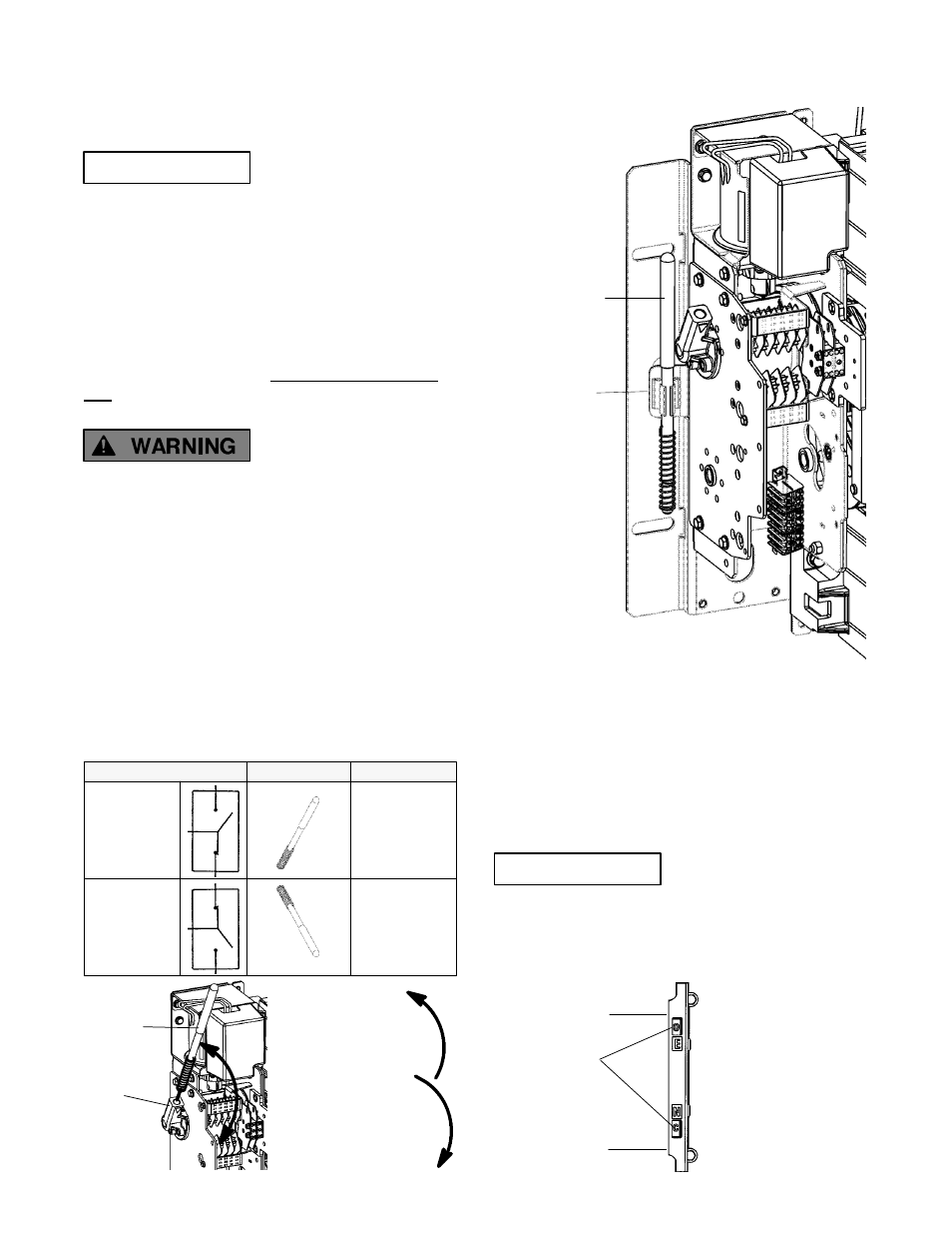
operator. See Figures 1–3 and 1–4 and Table B.
2. Move the maintenance handle up or down as shown
to manually operate the transfer switch. It should
operate smoothly without any binding. If it does not,
check for shipping damage or construction debris.
Table B. Maintenance handle positions.
ATS Position
Handle
Indicators
Normal
E
N
up
E = O
upper contacts open
N = C
lower contacts closed
Emergency
E
N
down
E = C
upper contacts closed
N = O
lower contacts open
maintenance
handle
left side of
transfer switch
storage clip
Figure 1-3. Maintenance handle & storage location.
3. Return the transfer switch to the Normal position.
Observe that the window indicators (right side) show
the top shaft O (open) and the bottom shaft C (closed).
Note: If Normal and Emergency connections are
reversed this operation is also reversed.
4. Remove the maintenance handle and store it on the
frame (left side) in the clips provided.
NOTICE
Verify that the maintenance handle has been
removed before proceeding!
Now continue to 2 – Voltage Checks on next page.
handle
hub
UP closes the
Normal source
contacts (lower)
DOWN closes the
Emergency source
contacts (upper)
frame
window
indicators
O is open
C is closed
Emergency
contacts
Normal
contacts
contact position
indicators (right side)