Installation, Continued), Engine starting contacts – Winco ASCO 300 J Design 600 Amp User Manual
Page 6: Auxiliary circuits
terminal block for engine start and
auxiliary circuit connections
left side of
transfer switch
COMMON
FEATURE 7
closes to start
FEATURE 8
opens to start
COMMON
FEATURE 14B
closed on emergency
FEATURE 14A
closed on normal
COMMON
FEATURE 14BA
closed on emergency
FEATURE 14AA
closed on normal
Engine Starting
Signals
5 amps, 32 V DC
5 amps resistive 28 V DC
or 120 V AC max.
TS Auxiliary Contacts
Feature 14A & 14B
10 amps, 32 V DC
10 amps 250 V AC
general purpose
Optional
TS Auxiliary Contacts
Feature 14AA & 14BA
10 amps, 32 V DC
10 amps 250 V AC
general purpose
INSTALLATION
(continued)
1---2
Engine Starting Contacts
Customer connections for engine control contact and
TS auxiliary contacts connections are located on
terminal block TB which is mounted on the front lower
left of the transfer switch. Refer to wiring diagram
provided with the Series 300 ATS and connect the
engine start wires to the appropriate terminals.
See Figure 1–1 and Table A.
Table A. Engine start
connections.
When normal
source fails
Terminals
on transfer
switch
contact closes
TB1 and TB2
contact opens
TB1 and TB3
Auxiliary Circuits
Connect auxiliary circuit wires to
appropriate terminals on transfer
switch terminal block TB as shown
on the wiring diagram provided
with this Automatic Transfer
Switch. Make the necessary
auxiliary connections by referring
to Section 5, Control Features.
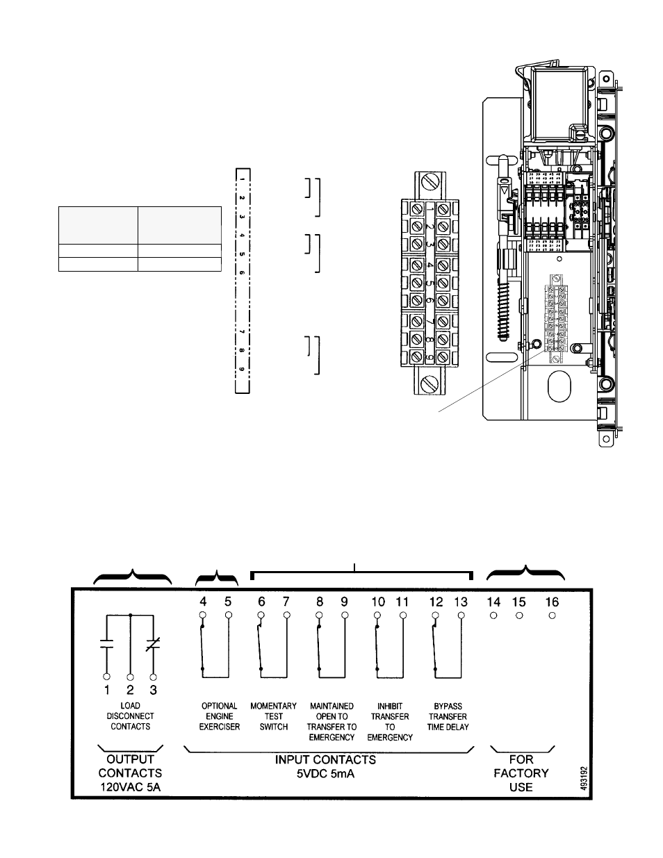
Connections to Controller
for other Control Features
(located on bottom of Controller)
Figure 1-1. Engine start and auxiliary circuit
terminal block TB located on the transfer switch.
for factory
use only
Remote Control Features Connections
(refer to the Wiring Diagram &
page 5–4 for DIP switch settings)
Each control contact must be suitable
for a 5 V DC low energy circuit.
Programmable
Engine Exerciser
connection,
if provided
(refer to
page 5–3)
Load Disconnect
Feature
Connections
(see Wiring Diagram
& refer to page 5–4
for DIP switch settings)
Figure 1-2. Input / output label on the Controller showing possible connections to the lower terminal block.