Crestron electronic Crestron Green Light DIN-HUB User Manual
Page 10
DIN Rail Cresnet
®
Distribution Hub
Crestron DIN-HUB
Connectors, Controls & Indicators
# CONNECTORS
1
,
CONTROLS &
INDICATORS
DESCRIPTION
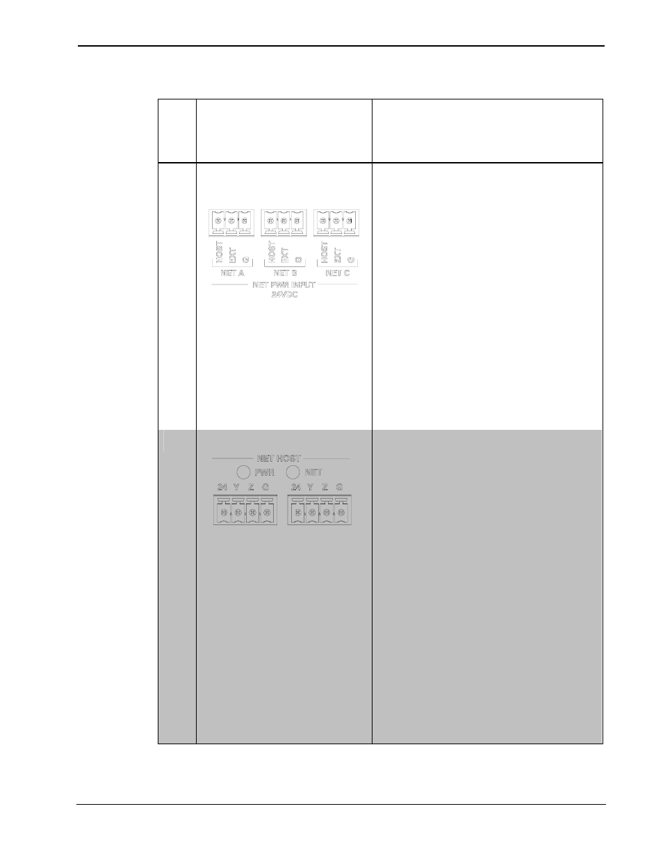
1
NET PWR INPUT
(A/B/C)
(3) 3-pin 3.5 mm detachable
terminal blocks
Cresnet power selection
connectors for each segment
Connect to external Cresnet
power supplies, or to “host”
power source via jumpers, to
power devices connected to the
NET A/B/C ports
Max Wire Size:
1.5 mm
2
(16 AWG)
Maximum Load per Segment:
75 Watts
(3.13 Amps @ 24 Volts DC)
2
NET HOST and LEDs
(2) 4-pin 3.5 mm detachable
terminal blocks, paralleled
Connects to Master NET port of
DIN-AP2 or other control
system, and loops through to
additional DIN Rail Cresnet
devices
Max Wire Size:
1.5 mm
2
(16 AWG)
Pin 1 (24): Power (24 VDC)
Pin 2 (Y): Data
Pin 3 (Z): Data
Pin 4 (G): Ground
(1) Green LED indicates
Cresnet power is supplied to
unit via either NET HOST port
(Continued on following page)
6
• DIN Rail Cresnet Hub: DIN-HUB
Operations & Installation Guide – DOC. 6671A