Fitting and operating, Adjustment of avr controls, Sx460 – Winco SX460 User Manual
Page 3
FITTING AND OPERATING
TD_SX460.GB_04.05_05_GB
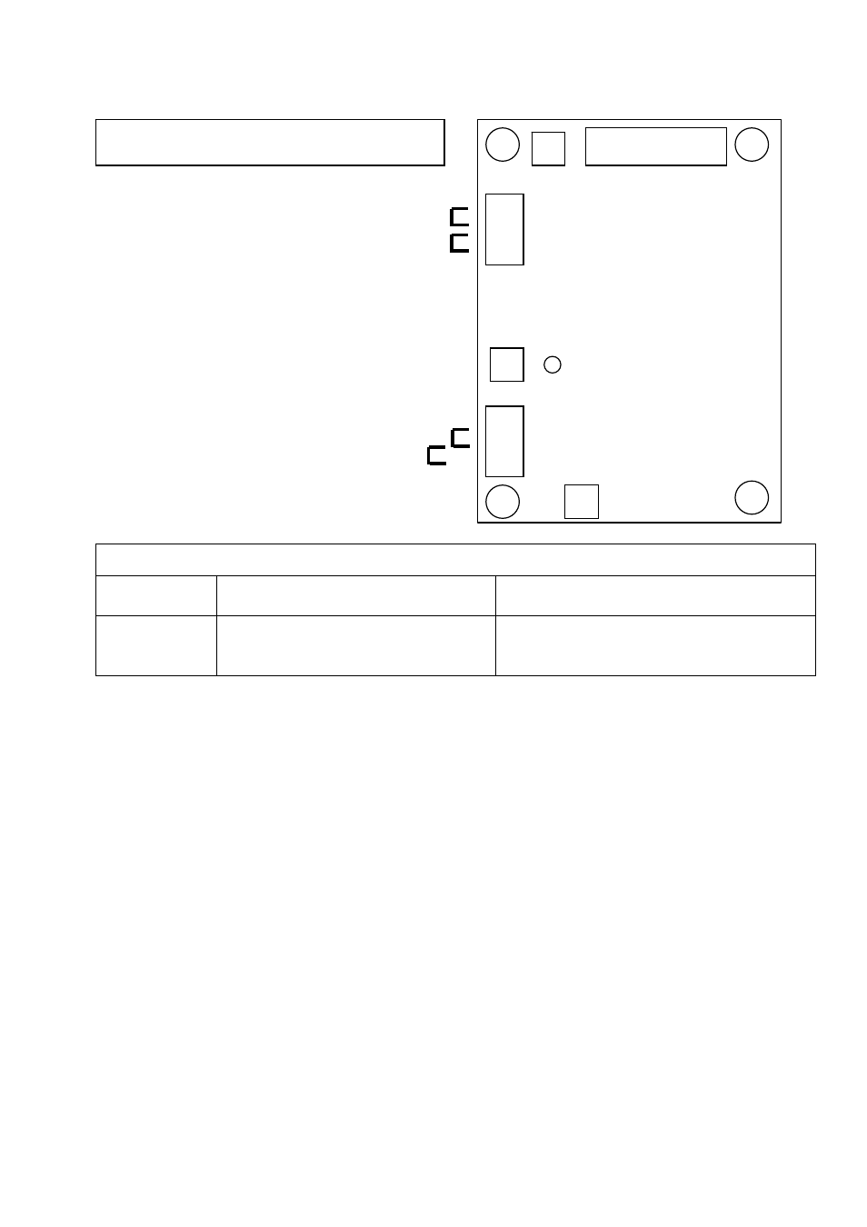
Remove link to connect a remote voltage trimmer
Link for 110V/120V AVR input
SUMMARY OF AVR CONTROLS
CONTROL FUNCTION
DIRECTION
VOLTS
TO ADJUST GENERATOR OUTPUT VOLTAGE
CLOCKWISE INCREASES OUTPUT VOLTAGE
STABILITY
TO PREVENT VOLTAGE HUNTING
CLOCKWISE INCREASE THE DAMPING EFFECT
UFRO
TO SET THE UFRO KNEE POINT
CLOCKWISE REDUCES THE KNEE POINT
FREQUENCY
ADJUSTMENT OF AVR CONTROLS
VOLTAGE ADJUSTMENT
The generator output voltage is set at the factory, but can
be altered by careful adjustment of the VOLTS control on
the AVR board, or by the external hand trimmer if fitted.
Terminals 1 and 2 on the AVR will be fitted with a shorting
link if no hand trimmer is required. Terminals 3 and 4 are
linked only for special low voltage applications.
CAUTION Do not increase the voltage above the rated
generator voltage. If in doubt, refer to the rating plate
mounted on the generator case.
CAUTION Do not ground any of the hand trimmer
terminals as these could be above earth potential. Failure
to observe this could cause equipment damage.
If a replacement AVR has been fitted or re-setting of the
VOLTS adjustment is required, proceed as follows:
CAUTION
1. Before running generator, turn the VOLTS control
fully anti-clockwise.
2. Turn remote volts trimmer (if fitted) to midway
position.
3. Turn STABILITY control to midway position.
4. Connect a suitable voltmeter (0-300V ac) across line
to neutral of the generator.
5. Start generator set, and run on no load at nominal
frequency e.g. 50-53Hz or 60-63Hz.
6. If the red Light Emitting Diode (LED) is illuminated,
refer to the Under Frequency Roll Off (UFRO)
adjustment.
7. Carefully turn VOLTS control clockwise until rated
voltage is reached.
8. If instability is present at rated voltage, refer to
stability adjustment, then re-adjust voltage if necessary.
9. Voltage adjustment is now completed.
VOLTS
F2 F1 6 7 8
4 3 2 1
60 C 50
UFRO ( Under Frequency Roll Off)
INDICATOR LED
STABILITY
FREQUENCY
SELECTION
SX460
REFER TO GENERATOR WIRING DIAGRAM
FOR CONNECTION DETAILS