Design detail – Winco SX460 User Manual
Page 2
DESIGN DETAIL
TD_SX460.GB_04.05_05_GB
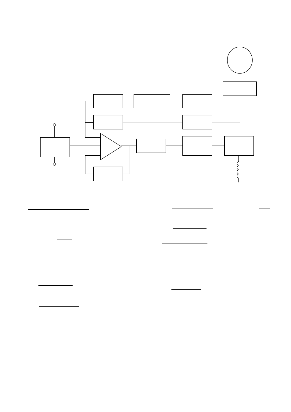
The main functions of the AVR are:
Potential Divider and Rectifier takes a proportion of the
generator output voltage and attenuates it. This input chain
of resistors includes the range potentiometer and hand
trimmer which adjust the generator voltage. A rectifier
converts the a.c. into d.c. for further processing.
The Amplifier (Amp) compares the sensing voltage to the
Reference Voltage and amplifies the difference (error) to
provide a controlling signal for the power devices. The
Ramp Generator and Level Detector and Driver infinitely
control the conduction period of the Power Control Devices
and hence provides the excitation system with the required
power to maintain the generator voltage within specified
limits.
The Stability Circuit provides adjustable negative ac
feedback to ensure good steady state and transient
performance of the control system.
The Low Hz Detector measures the period of each
electrical cycle and causes the reference voltage to be
reduced approximately linearly with speed below a
presettable threshold. A Light Emitting Diode gives
indication of underspeed running.
The Synchronising circuit is used to keep the Ramp
Generator and Low Hz Detector locked to the generator
waveform period.
The Low Pass Filter prevents distorted waveforms
affecting the operation of the AVR.
Power Control Devices vary the amount of exciter field
current in response to the error signal produced by the
Amplifier.
Suppression components are included to prevent sub
cycle voltage spikes damaging the AVR components
and also to reduce the amount of conducted noise on
the generator terminals.
The Power Supply provides the required voltages for
the AVR circuitry.
Suppression
Low Pass
Filter
Synchronising
Ciruit
Low Hz
Detection
Power
Control
Devices
Level
Detector &
Driver
Reference
Voltage
Stability
Circuit
Potential
Divider &
Rectifier
Power
supply
Ramp
Generator
Generator
Amp
Voltage
Sensing
Hand
Trimmer
Exciter
Field