Winco PSS70000 User Manual
Page 7
60706-124
Page 5
60541
Two (2) Regulator System (L.P. Vapor only)
1
2
3
4
UNIT OFF
TANK PSI
10-15 lbs
7-11 in
7-11 in
4-6 oz
4-6oz
STARTING
TANK PSI
10-15 lbs
7-11 in
7-11 in
4-6 oz
4-6 oz
NO LOAD
TANK PSI
10-15 lbs
7-11 in
7-11 in
4-6 oz
4-6 oz
FULL LOAD
TANK PSI
10-15 lbs
7-11 in
7-11 in
4-6 oz
4-6 oz
Natural Gas
1
3
4
UNIT OFF
LINE PSI
7-11 in
7-11 in
4-6 oz
4-6 oz
STARTING
LINE PSI
7-11 in
7-11 in
4-6 oz
4-6 oz
NO LOAD
LINE PSI
7-11 in
7-11 in
4-6 oz
4-6 oz
FULL LOAD
LINE PSI
7-11 in.
7-11 in
4-6 oz
4-6 oz
Notice the preceding tables give two (2) different units of
measuring fuel pressure. The first is with a pressure gauge
calibrated in ounces per square inch. The second and most
accurate is the use of a simple water manometer. A manometer
is calibrated in inches of water column.
LP LIQUID WITHDRAWAL SYSTEMS
When installing a unit equipped the LP liquid withdrawal a
primary regulator is not required on the supply tank. The supply
line is connected to a liquid withdrawal valve on the supply tank
and ran directly to the fuellock strainer mounted on the engine
generator set. Normally a 3/8 inch copper line is acceptable for
this type of fuel installation. You must be sure that the valve you
have connected to on the supply tank is in fact a liquid supply
valve and has a drop tube inside the tank that is pulling fuel from
the bottom of the supply tank. Before starting the unit you must
confirm that you have a good liquid supply at the unit. Engine
generators sets equipped for liquid withdrawal will not run
properly when supplied with high pressure vapor fuel.
LUBRICATION
Before starting the engine, check the oil level in the crankcase. If
it is low, refill to the full mark with the proper weight/grade of oil
as recommended by the engine manufacturer’s maintenance
instructions. The necessity of using the correct oil, and keeping
the crankcase full cannot be over emphasized. Failure to use
the proper oil and keep the crankcase properly filled will cause
excessive engine wear and shorten its useful life.
COOLANT
Before starting the engine, check the coolant level in radiator. If it
is low, refill as specified in the engine manufacturer’s mainte-
nance instructions. The radiator should be filled to about 1 inch
below the filler neck.For additonal information on engine coolant
requirements see engine manufacturer’s maintenance instruc-
tions.
Size of pipe normally required for generators operating on
NATURAL/LP gas.
up to 25 feet* over 25 feet*
PSS20000
1" pipe not recommended
PSS35000
1" pipe use a
PSS70000
2" pipe two regulator system
* Allow an additional 3 feet for each standard elbow. Do not
use ‘street ells’ (restrictive)*
**** CAUTION ****
EQUIPMENT DAMAGE - Be careful when sealing gas joints.
Excessive sealing compound can be drawn into the solenoid,
regulator or carburetor causing an engine malfunction.
FUEL PRESSURE (vapor system)
Correct fuel pressure cannot be stressed enough. The most
common cause for inoperative systems is an inadequate or
incorrect fuel pressure. Performance of the engine is in direct
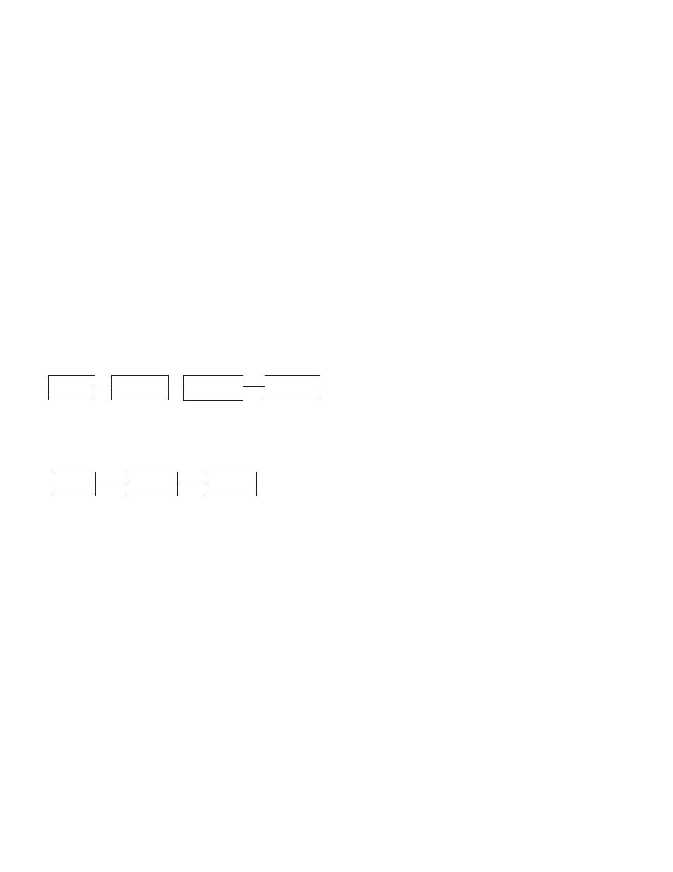
relation to the correctness of the fuel system. Shown below is a
block diagram of a typical L.P. or N.G. Installation.
Supply
Primary
Secondary
Generator
Tank
Regulator
Regulator
Set
1 2
3
4
TWO (2) REGULATOR FUEL SYSTEM
Supply
Primary
Generator
Tank
Regulator
Set
1
2
3
SINGLE REGULATOR FUEL SYSTEM
Reference numbers 1 through 3 in the block diagrams above
are fuel lines supplied by customer.
Reference number 4 is the engine generator set.
Below is a table of the fuel pressure reading at each reference in
the system.
Fuel Pressure Table
Single Regulator (L.P. Vapor only)
1
2
3
UNIT OFF
TANK PSI
7-11 in
7-11 in
4-6 oz
4-6 oz
STARTING
TANK PSI
7-11 in
7-11 in
4-6 oz
4-6 oz
NO LOAD
TANK PSI
7-11 in
7-11 in
4-6 oz
4-6 oz
FULL LOAD
TANK PSI
7-11 in
7-11 in
4-6 oz
4-6 oz