Procedure – Winco ULPSS8B2W/E User Manual
Page 13
3
075-00
60706-2
PROCEDURE
Engine Generator Set only
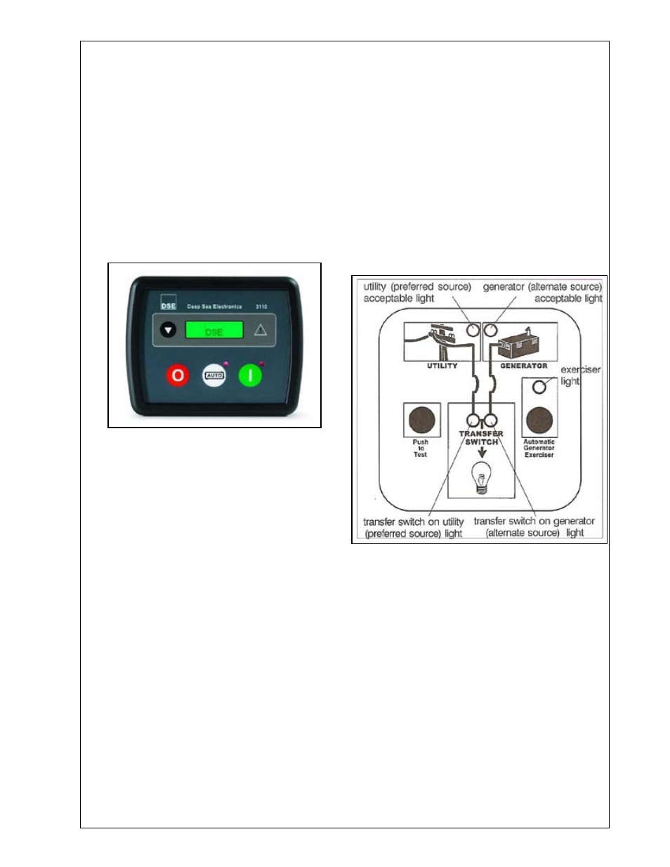
The engine control module (ECM) is manufactured
by Deep Sea Electronics. Model 30 is used on
this engine generator set. See picture below. Ad-
ditional information on the DSE 30 is on pages 4
through 7.
Manual Operation
Press and release the red Stop/Reset button. Then
press and release the green Start Engine button.
The engine generator will crank and start automati-
cally. If the engine fails to start correct the problem
before proceeding.
With the engine running smoothly, check the no load
voltage and frequency at wire # and # 4 (L2 and
L6 in the ASCO ATS) on the generator terminal block
in the ATS. The voltage should be 240 volts plus or
minus nominal. The frequency should be between
6.5 to 62 hertz (Hz). The voltage should also be
checked between the hot terminals (L2 and L6) and
the neutral to be certain of a balanced voltage output
and a solid neutral connection. The voltage should
be about on half of the line to line voltage.
** NOTICE **
If for any reason during the check out procedures
the voltage and frequency are not correct, press the
Stop/Reset button and correct the trouble before
proceeding.
After verifying the voltage and frequency are correct,
press the Stop/Reset button. This will shut off the
engine immediately.
Transfer Switch & Engine Generator
Automatic (remote) Operation
This procedure checks the electrical operation of
the automatic transfer switch. If the actual operation
does not follow this procedure, consult the trou-
blshooting section in the transfer switch manual.
. Turn on the preferred source (utility) circuit
breaker. The utility source acceptable light should
now come on as well as the transfer switch on utility
light. If these lights fail to come on recheck your
incoming power to insure you have 240 volts nomi-
nal. If not, troubleshoot your utility source before
continuing.
******************
***** WARNING *****
******************
PERSONAL INJURY HAZARD - Install front cover
in transfer switch before operation. An electrical sys-
tem fault could cause a flash and severe personal
injury.
2. Press and release the Auto button on the en-
gine control module (ECM). The auto mode icon will
appear on the screen. The unit is now ready to be
operated from the Automatic Transfer Switch.
3. Turn on the altenate source (generator) curcuit
breaker.
4. Press and hold the
Push to Test button until
the generator (alternate source) acceptable light
comes on and stays on. Then release the button.
This will start up your generator set.
This light indicates that the generator is running and
the output voltage and frequency are within accept-
able limits. Under normal conditions this light should
come on in 5 to 0 seconds. If the light does not
come on and stay on a malfunction has occurred.
Either the unit didn’t start or the voltage or frequency
is incorrect. Correct the problem before continuing.