Dc electrical interconnection, Initial start up – Winco ULPSS8B2W/E User Manual
Page 12
075-00
2
60706-2
Because of the many different types of service,
feeder, and distribution equipment, no specific wiring
instructions can be provided. It is, however, recom-
mended that
copper wire be used. In all cases it is
essential that while the load is connected to the gen-
erator, there can be absolutely no feedback from the
generator to the power line or the power line to the
generator. When properly installed, the normal ATS
control and safety systems will eliminate all paths for
feedback. Check with your local electrical inspector
on applicable local, state and federal codes.
******************
***** WARNING *****
******************
A service disconnect must be installed in front of the
ATS panel as the ATS is not service enterance rated.
This will alow you to test the generator under load.
Should you ever have to work on the switch, you will
be able to disconnect the power and work on the
switch cold without having the power company pull
your meter.
To wire the automatic transfer switch into the exist-
ing wiring, first determine which circuits will be on
the emergency load circuit. If the entire load is to
be transferred, the transfer switch can be wired in
directly after the watt-hour meter and the service
enterance, providing the service enterance ampere
rating is within the transfer switch’s rated capability.
If only specific circuits are to be powered under
emergency power failure conditions, and additional
distribution panel designated “emergency distribution
panel” must be installed.
All selected emergency circuits are removed from
main distribution panels and reinstalled in the emer-
gency distribution panel. Suggested circuits: freez-
er, refrigerator, furnace, emergency lights, sump
pump, emergency outlet circuits, etc. Total running
load must not exceed generator rating.
DC ELECTRICAL
INTERCONNECTION
**** CAUTION ****
Never run the AC and DC wiring in the same con-
duit.
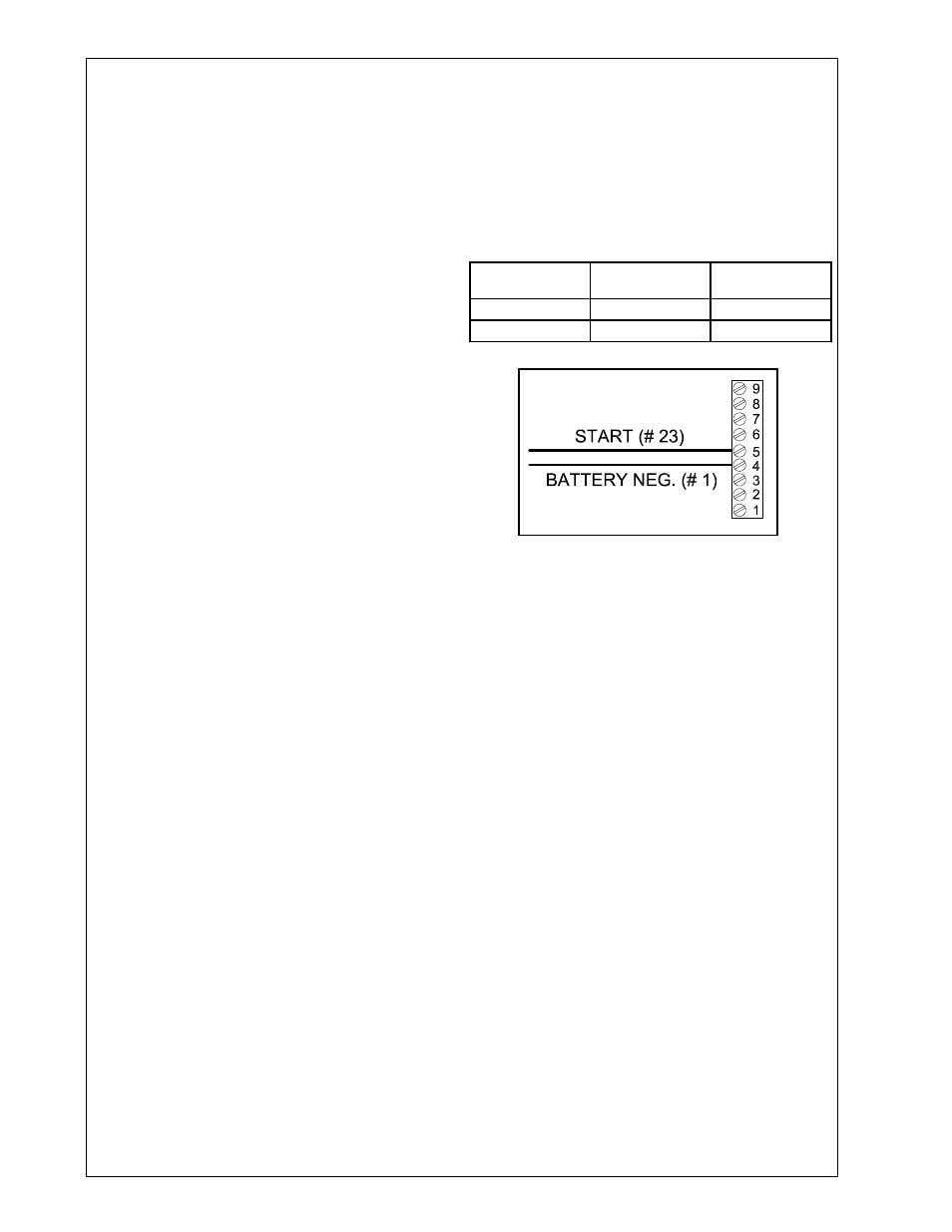
ASCO 165 UL SWITCH
Your DC connection points in the ASCO 65 UL ATS
are on the terminal block in the upper right hand
corner of the ATS panel. The terminal block (TB7)
is numbered through 9. These terminals will
accept # 22 - # 4 AWG stranded wire. It is recom-
mended that you use # 6 AWG for distances up
to 200 feet. You need to run two (2) wires from the
engine generator set to the transfer switch. You
will be using terminals 4 and 5, wire Start # 23 will
connect to terminal # 5 and wire Battery Negative #
will connect to terminal # 4. See table and illustra-
tion below.
WIRE #
PURPOSE
RECOMMENDED
COLOR
# 23
Start
Black
# 1
Battery Negative
White
� Fuel line protected and a moisture trap in
stalled (may be required for NG).
� LP/NG pressure OK. 4-6 oz. (7- in. WC).
� Battery connections clean and tight.
� Battery fully charged.
� All AC and DC wiring installed and properly
protected.
* Refer to engine owners manual for proper
levels and types.
After completing the above checklist, the engine
generator set is ready for the initial start-up test.
INITIAL START UP
******************
***** WARNING *****
******************
DO NOT jump start these engine generator sets.
Starting these units on a low battery of jump start-
ing them will cause damage to the engine control
module.
Use the following checklist to verify correct in-
stallaion before starting the engine:
� Engine oil.* Check level & fill as required with
proper grade/quantity.
� Unit mounting base properly bolted down.
� Clearance for service and maintenance on all
sides.
� Proper fuel line material and size.
� All fuel line connections tight.