Winco PSS12H4W/A User Manual
Page 6
PAGE 4
60706-167
4062-00
ENGINE GENERATOR SET MOUNTING
The unit’s main frame should be bolted solid to a four to
six inch thick cement pad. The engine-generator is
mounted on a sub-frame which is isolated with special
shock mounts on the main frame. This allows the engine-
generator to vibrate without affecting the control panel on
the main frame.
Do not install any shock mounts between the base
frame and the concrete pad. Engine vibration will be
transmitted to the control panel causing erroneous start/
stop cycles and premature control failure.
The unit should be mounted to allow for ample working
room around it. A general rule to follow is three (3) feet
clearance on all sides. NFPA 37 requires at least 3 feet
clearance from any structures having combustible
adjacent walls and 5 feet from openings in walls. Particu-
lar attention should be paid to the direction of the hot air
discharge and exhaust discharge. Unit location should be
such that these discharges are not allowed to be drawn
back in through an open window or door.
FUEL INSTALLATION
The fuel supply should be as close as possible to the
engine. This will reduce the installation cost of fuel runs.
The information in this manual is offered to assist you in
providing the proper fuel for your engine. However, this
information is only provided to inform you of the engine’s
requirements and assist in making you aware of the
decisions you must make. In no case should the
instructions or information provided be interpreted to
conflict with any local, state or national codes. If in doubt,
always consult your local fire marshal or gas supplier.
*************
***** WARNING ****
*************
FIRE HAZARD - All fuel runs should be installed by a
licensed fuel supplier.
To connect the fuel line to the generator set you will
have to remove the end panel on the exhaust end of the
enclosure. With this panel remove you will be able to
access the complete fuel system on the unit. You will
need to do two things with this panel removed.
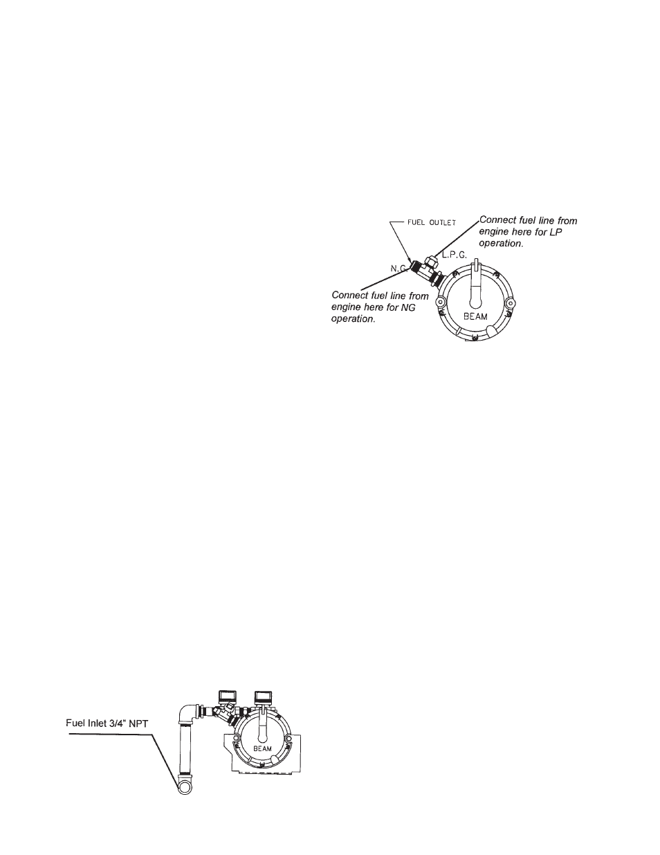
First you will connect your incoming fuel line to the 3/4
inch NPT elbow provided inside the enclosure. This
elbow is shipped with a plastic cap plug installed to insure
the fuel system stays clean.
For all vapor fuel systems the delivery pressure of the
fuel to the fuel solenoid on the unit must be four to six
ounces psi (per square inch) or 7 to 11 inches W.C.
(Water column). These fuel pressures are critical; failure
to provide the proper fuel pressure can cause many
problems ranging from a unit that will not start to causing
damage to the fuel system.
The second thing you need to do is ensure that your unit
is connected for the correct fuel. These units come
capably of working on either LP or NG fuel. It just
depends on where the fuel line from the engine is
connected to the demand regulator.
These units are normally tested on Natural gas and will
have the fuel line connected to the N.G. port on the fuel
outlet tee. If you are going to operate on LPG you will
need to move the fuel line from the NG port to the LPG
port on the fuel outlet tee. These two ports have different
orifice inserts installed in them, which provide proper
engine operation with no further adjustments.
When moving the fuel line from one port to the other be
sure not to kink or bend the line. Use as large a sweeping
curve as possible and never shorten the fuel line. For
proper operation the fuel line must stay the same length
as it was shipped.
INSTALLING THE FUEL LINE
** NOTICE **
The engine generator sets are properly adjusted before
they leave the factory. A tag is attached to the unit that
specifies the fuel, natural gas (NG) or propane vapor (LP)
that the unit was set up and tested on.
Line Size
Unit location will determine the size of fuel line that is
required to supply the engine with a constant fuel pres-
sure and volume. Refer to the tables below for fuel line
size, fuel consumption and recommended tank size. For
distances of 50 feet and over, a two regulator fuel system
is recommended. This is accomplished by installing a
primary regulator at the tank which will reduce the tank
pressure down to 10 to 15 lbs. A secondary regulator is
installed to further reduce the fuel pressure to the required
four (4) to six (6) oz operating pressure. This secondary
regulator must be at least 10 feet from the engine genera-
tor set, any closer installation will require a larger line be
installed to provide a fuel reservoir. This is also true for
the single dual stage regulators, it should also be mini-