Initial start up – Winco PSS12H4W/A User Manual
Page 10
PAGE 8
60706-167
4062-00
*************
***** WARNING *****
*************
A service disconnect must be installed in front of the
A.T.S. panel as the A.T.S is not service entrance rated.
This will allow you to test the generator under load.
Should you ever have to work on the switch, you will be
able to disconnect the power and work on the switch cold
without having the power company pull your meter.
To wire the automatic transfer switch into the existing
wiring, first determine which circuits will be on the
emergency load circuit. If the entire load is to be trans-
ferred, the transfer switch can be wired in directly after the
watt-hour meter and the service entrance, providing the
service entrance ampere rating is within the transfer
switch’s rated capability.
If only specific circuits are to be powered under emer-
gency power failure conditions, an additional distribution
panel designated “emergency distribution panel” must be
installed.
All selected emergency circuits are removed from main
distribution panels and reinstalled in the emergency
distribution panel. Suggested circuits: freezer, refrigera-
tor, furnace, emergency lights, sump pump, emergency
outlet circuits, etc. Total running load must not exceed
generator rating.
D.C. ELECTRICAL INTERCONNECTION
*******CAUTION******
Never run the AC and DC wiring in the same conduit.
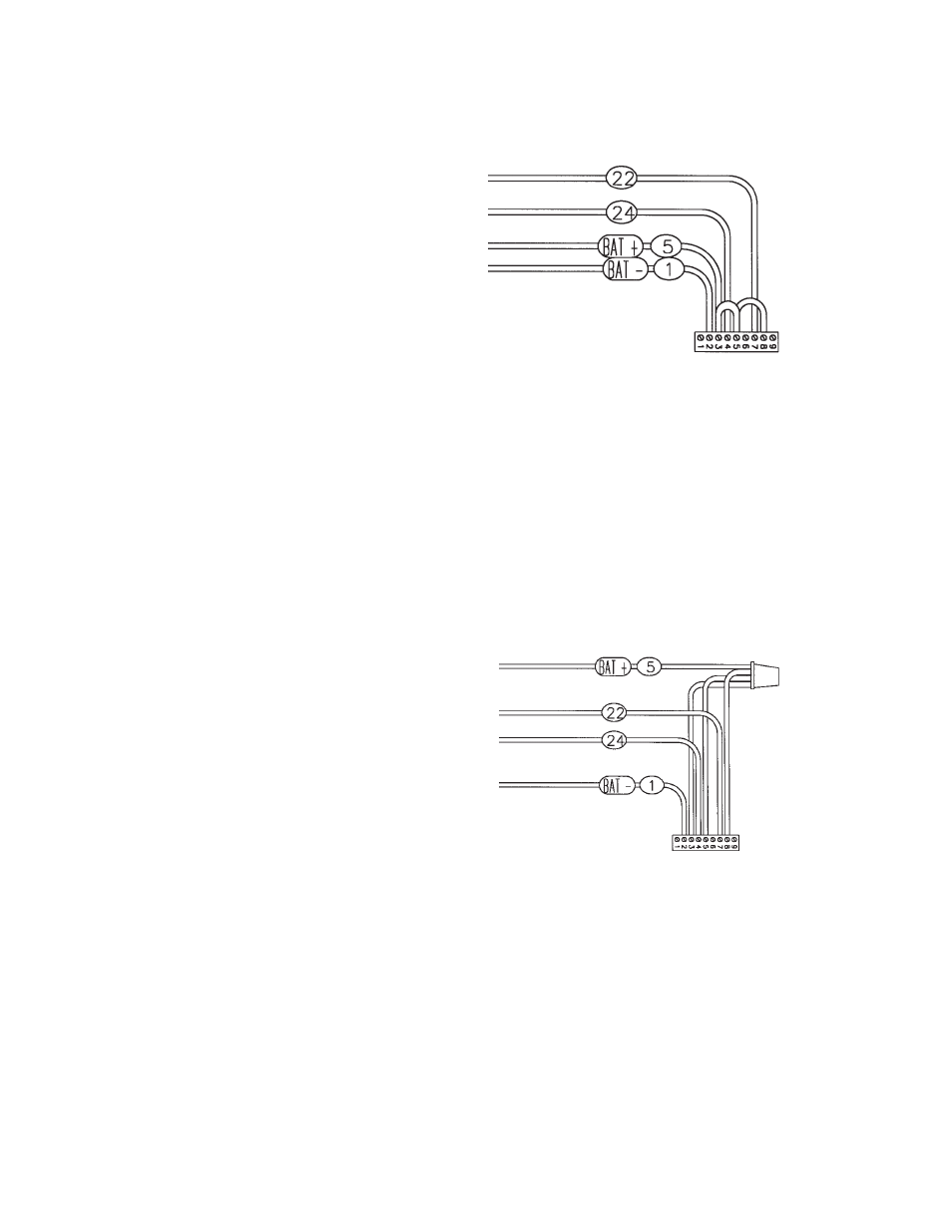
ASCO 165 UL SWITCH
Your DC connection points in the ASCO 165 UL ATS
are on the terminal block in the upper right hand corner of
the ATS panel. The terminal block (TB7) is numbered 1
through 9. These terminal will accept #22 - #14 stranded
wire. It is recommended that you use #16 for distances
up to 200 feet.
You need to run four (4) wires from the engine generator
set to the transfer switch, see table below.
Wire #
Purpose
Recommended Color
#5
Battery positive
Black
#1
Battery Negative
White
#24
Fuel Solenoid
Red
#22
Start
Orange
You can use any color you want, these color codes are
just a recommendation. The wires terminate on TB7 as
follows:
Wire #
Color
TB7 Terminal
#5
Black
#3
#1
White
#2
#24
Red
#4
#22
Orange
#7
Jumpers will need to be installed as follows:
Wire #
Color
TB7 Terminals
#5
Black
#3 & #5
#5
Black
#5 & #8
The following is a optional way to interconnect the
Generator and the Transfer Switch. The wires terminate
on TB7 as follows:
Wire #
Color
TB7 Terminal
#1
White
#2
#24
Red
#4
#22
Orange
#7
The following leads are wire nutted together:
Wire #
Color
From
#5
Black
Generator
#5
Black
TB7 #3
#5
Black
TB7 #5
#5
Black
TB7 #8
INITIAL START UP
*************
***** WARNING *****
*************
DO NOT jump start these engine generator sets. Starting
these units on a low battery or jump starting them will
cause damage to the engine control module.
Use the following check list to verify correct installa-
tion before starting the engine:
Engine oil.* Check level & fill as required with
proper grade/qty.
Unit mounting base properly bolted down.
Clearance for service and maintenance on all
sides.
Optional Connections