Basic information, Intended uses, Restricted uses – Winco HPS9000E User Manual
Page 4: Unit capabilities
HPS 12/97
Page 2
60707-112
CAUTION: EQUIPMENT DAMAGE
CAUTION MUST BE EXERCISED TO PREVENT
OVERLOADING EITHER OF THE GENERATORS
120 VOLT OUTPUT CIRCUITS (A OR B).
Check the appliance or tool nameplates for the current and
voltage to insure compatibility. Remember that power taken
from receptacle C reduces the power available at both A and
B. Any remaining 120 volt loads should be equally divided
between A and B. Failure to split the load will cause
permanent damage to the stator. Although circuit breakers
are provided, damage due to overloading constitutes abuse
and will not be warranted. Refer to the generator nameplate
for your unit's capabilities.
Starting Electric Motors - Electric motors require much
more current (amps) to start them than to run them. Some
motors, particularly low cost split-phase motors, are very
hard to start and require 5 to 7 times as much current to start
them as to run them. Capacitor motors are easier to start
and usually require 2 to 4 times as much current to start
them as to run them. Repulsion Induction motors are the
easiest to start and usually require 1 1/2 to 2 1/2 times as
much to start them as to run them.
Most fractional horsepower motors take about the same
amount of current to run them whether they are of
Repulsion-Induction (RI), Capacitor (Cap), or Split-Phase
(SP) type. The chart below shows the approximate current
required to start and run various types and sizes of 120 volt
60 cycle electric motors under average load conditions.
RUNNING
STARTING AMPS
HP
AMPS SP
CAP
RI
1/6
3.2
16 TO 22
6 TO 13
5 TO 8
1/4
4.5
22 TO 32
9 TO 18
7 TO 12
1/3
5.2
26 TO 35
10 TO 21
8 TO 17
1/2
7.2
NOT MADE 14 TO 29
11 TO 18
1
13.0
NOT MADE 26 TO 52
20 TO 33
The figures given above are for an average load such as a
blower or fan. If the electric motor is connected to a hard
starting load such as an air compressor, it will require more
starting current. If it is connected to a light load, or no load
such as a power saw, it will require less starting current.
The exact requirement will also vary with the brand or design
of the motor.
Self-excited generators respond to severe overloading
differently than the power line. When overloaded, the engine
is not able to supply enough power to bring the electric
motor up to operating speed. The generator responds with
high initial starting current, but the engine speed drops
sharply. The overload may stall the engine. If allowed to
operate at very low speeds, the electric motor starting
winding will burn out in a short time. The generator winding
might also be damaged.
CAUTION: EQUIPMENT DAMAGE
RUNNING THE GENERATOR SET UNDER THESE
CONDITIONS MAY RESULT IN DAMAGING THE
GENERATOR STATOR AS WELL AS THE MOTOR
WINDING.
INTENDED USES
These engine generator sets have been designed
primarily for portable use. Both 120 and 240 volt AC
receptacles are provided in the 'control panel' to plug in
your loads (lights, portable tools, and small appliances).
These units are dual wound generators, therefore the 120
Volt loads must be equally split with 1/2 of the rated
capacity available on each of the two 120 Volt circuits. See
unit capabilities for further explanation.
These portable units require large quantities of fresh air
for cooling of both the engine and the generator. Fresh air
is drawn from both the engine end and the generator end
and is exhausted at the center of the unit. For safety, long
life and adequate performance, these units should never
be run in small compartments or enclosed areas, without
positive fresh air flow.
RESTRICTED USES
DO NOT remove from the cradle assembly. Removal of
the generator from the cradle assembly may cause
excessive vibration and damage to the engine generator
set.
DO NOT install and operate these portable generators in a
small compartment., i.e. generator compartment of
vehicles, motor homes or travel trailers. These
compartments will not allow enough free flow fresh air to
reach the engine generator set for cooling and will cause
the unit to overheat damaging both the engine and the
generator. Small compartments will also develop hot
spots where there is very little air flow and may cause a
fire.
DO NOT attempt to operate at 50 cycles. These units are
designed and governed to operate at 60 Cycles only.
UNIT CAPABILITIES
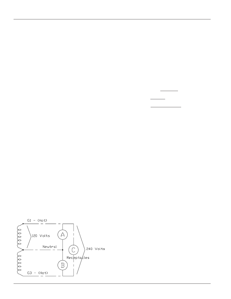
Generator Connections - The diagram below represents
a typical 4000 watt generator. Receptacles A and B are
the two 120 Volt duplex receptacles. Up to 2000 watts at
120 volts (16.6 Amps) can be taken from the generator at
each of the receptacles. This generator produces 120 and
240 volt, 60 Hz (Hertz), AC (Alternating Current).
BASIC INFORMATION