Optional fuel solenoid installation instructions – Winco HPS9000E User Manual
Page 11
Page 9
60707-112
HPS 12/97
OPTIONAL FUEL SOLENOID
INSTALLATION INSTRUCTIONS
(see page 4 Installing the Fuel Line)
PARTS REQUIRED
1. ¾” 12 volt DC vapor fuel solenoid, WINCO part number
42942-000
2. 120 volt AC single pole relay (SPDT), WINCO part
number 59944-001.
3. Single pole push button switch, normal open with
momentary contacts. Purchase locally.
4. Electrical box and cover, 4” X 4”. Purchase locally
ASSEMBLY INSTRUCTIONS
a. Mount the relay inside the electrical box and the push
button switch in the cover of the box. Mount the box in a
convenient location on the unit
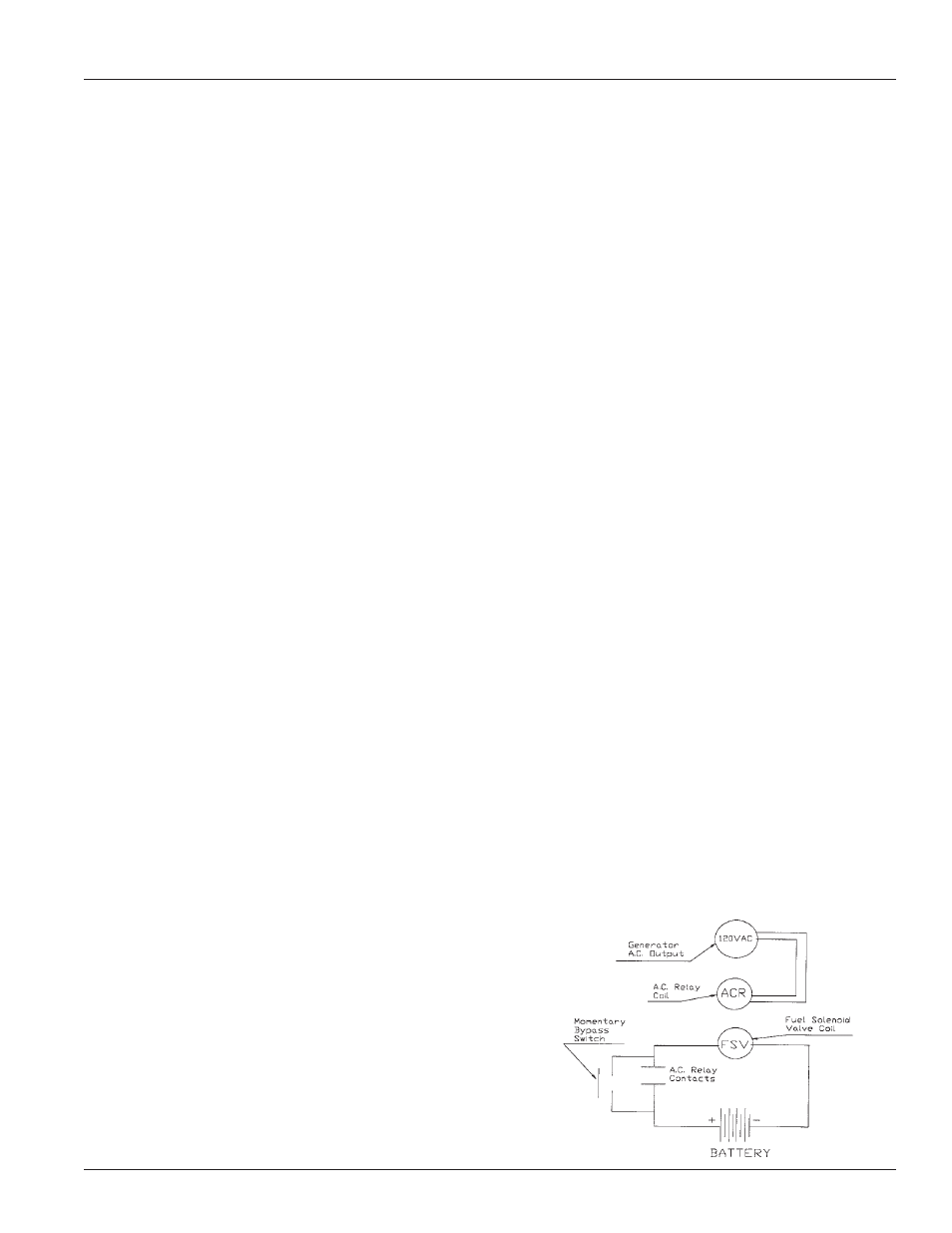
b. Connect the coil leads of the 120 volt AC relay to the
generator output. This may be done either by installing a
power cord and plugging it into one of the 120 volt outlets,
or by hard wiring it to the generator output leads in the end
cover of the generator.
c. Connect one of the leads on the fuel solenoid to the
negative side of the battery.
d. Connect the positive side of the battery to one of the
normally open contacts on the 120 volt AC relay. Also
connect one side of the momentary push button switch to
the same contact on the 120 volt AC relay.
e. Connect the second lead from the fuel solenoid to the
other side of the normally open contacts on the 120 volt AC
relay. Also connect the other side of the push button switch
to the same contact on the 120 volt AC relay.
f.
To start the unit the push button switch must be
depressed and held until the unit starts up and the
generator has time to build output, about one to two
seconds after the engine reaches operating speed.
g. At that time the 120 volt AC relay will close and the fuel
solenoid will remain powered through the relay. If the
generator or engine should fail, the AC output from the
generator will disappear. The relay will open from the loss
of power, closing the fuel solenoid, shutting off the fuel flow.
b. Receptacles - Quality receptacles have been utilized.
If a receptacle should become cracked or otherwise
damaged, replace it. Using damaged or cracked
receptacles can be both dangerous to the operator
and destructive to the equipment.
CLEANING
Remove dirt and debris with a cloth or brush. DO NOT use
high pressure spray to clean either the engine or the
generator. This high pressure spray could contaminate the
fuel system and the generator components.
1. Keep the air inlet screen on both the engine and
generator free of any dirt or debris to insure proper
cooling. At least yearly remove the blower housing on
the engine and clean the chaff and dirt out of the engine
cooling fins and flywheel. Clean more often if
necessary. Failure to keep these areas clean may
cause overheating and permanent damage to the unit.
2. Periodically clean muffler area to remove all grass, dirt
and combustible debris to prevent a fire.
3. On engine mufflers equipped with spark arresters, the
spark arrester must be removed every 50 hours for
cleaning and inspection. Replace if damaged.
TROUBLESHOOTING HINTS
PROBLEM (SYMPTOMS) POSSIBLE CAUSES
——————————————————————————
Won’t Start
*Low Oil Level.
*Fouled spark plug.
*Out of fuel.
*Stop switch in stop position.
——————————————————————————
Voltage too low
*Engine speed is too low.
*Generator overloaded.
*Defective rectifier.
*Defective stator.
*Defective rotor (field).
——————————————————————————
Circuit Breaker
*Defective load.
Trips
*Defective receptacle.
——————————————————————————
Voltage too high
*Engine speed is too high.
——————————————————————————
Generator
*Overloaded.
overheating
*Insufficient ventilation.
——————————————————————————
No output voltage
*Short in load (disconnect).
*Broken or loose wire.
*Defective receptacle.
*No residual magnetism
(in generator).
*Defective stator.
*Defective rotor (field).
*Shorted capacitor.
*Defective rectifier.
——————————————————————————