Day night mode t266 only, Output #3 analog 0 to 10 vdc, Wiring – Viconics T266 User Manual
Page 2
Page: 4
Page: 5
Page: 6
A
Output no. 1 ( controlled device )
Type
0
Not installed
1
Relay, thermal relay, two position motor
Isolated Triac
2
Normally open thermal valve
Isolated Triac
3
Normally close thermal valve
Isolated Triac
4
"SSR" with 24 Vac input
Isolated Triac
5
"SSR" with 3-32 Vdc input
Pulsed 0/5 Vdc
6
0 to 10 Vdc actuator, voltage relay or "SCR" *
0 to 10 Vdc
* If output #1 is ordered A=6, the change over input is not available
B
Output no. 2 ( controlled device )
Type
0
Not installed
1
Relay, thermal relay, two position motor
Isolated Triac
2
Normally open thermal valve
Isolated Triac
3
Normally close thermal valve
Isolated Triac
4
"SSR" with 24 Vac input
Isolated Triac
5
"SSR" with 3-32 Vdc input
Pulsed 0/5 Vdc
C
Output no. 1 and 2 control mode
1
Heating, reverse acting, ( RA )
∗ Standard
2
Cooling, direct acting, ( DA )
3
Heating, RA ( no. 1 ) and cooling, DA ( no. 2 )
4
Cooling, DA ( no. 1 ) and heating, RA ( no. 2 )
D
Main control sensor location
1
Room, inside thermostat, or ( duct return air**)
∗ Standard
2
Duct supply air **
** Order with S60 or S70 sensor
E
Setpoint adjustment
1
User adjustable
∗ Standard
2
Blind cover
F
Scale
1
10
°C to 32 °C
∗ Standard
2
50
°F to 90 °F
G
Output no. 3
Damper changeover input
1
Normally cooling, ( DA )
Common dry contact for all thermostats
2
Normally heating, ( RA )
Common dry contact for all thermostats
3
Automatic
Duct supply sensor **
4
Automatic
with recirculation
Duct supply sensor **
** Order with S60 or S70 sensor
H
Future option
0
Unused
∗ Standard
WIRING
NOTE: WITH THE PROPER CODES, TERMINALS 5, 6, 8 AND 9 CAN BE
WIRED TOGETHER BETWEEN EACH THERMOSTAT IF POLARITY IS RESPECTED
Power supply 24 Vac -15% +10%
50/60 HZ 2 VA
COMMON
24 VAC
24VAC
5
6
POWER SUPPLY 24 Vac.
IMPORTANT: IF USING A COMMON TRANSFORMER
RESPECT POLARITY (COMMON AND 24 VAC)
BETWEEN EACH THERMOSTAT
Day night mode T266 only
CLOSE =
NIGHT
SET BACK
COMMON
INPUT
DAY / NIGHT 6
8
DAY NIGHT MODE
1 CONTACT USED FOR ALL
THERMOSTAT USING THE
SAME TRANSFORMER
Output #1 code A= 1, 2, 3 & 4 Triacs
Output #2 code B= 1, 2, 3 & 4 Triacs
RELAY OR THERMAL
VALVE 24 VAC
CONTACT
OUTPUT
1
2
OUTPUT #1 AND/OR #2 USING RELAY WITH ISOLATED TRANSFORMER
R
24VAC
3
4
AND / OR
USE TERMINALS 3 & 4 FOR OUTPUT #1
USE TERMINALS 1 & 2 FOR OUTPUT #2
Output #1 code A= 1, 2, 3 & 4 Triacs
Output #2 code B= 1, 2, 3 & 4 Triacs
RELAY OR
24 VAC
THERMAL VALVE
CONTACT
OUTPUT
COMMON
24 VAC
24VAC
5
6
OUTPUT #1 AND/OR #2 USING SAME TRANSFORMER TO OUTPUT
3
4
AND / OR
1
2
USE TERMINALS 3 & 4 FOR OUTPUT #1
USE TERMINALS 1 & 2 FOR OUTPUT #2
Output #1 code A= 5 Pulsed 0/5 Vdc
Output #2 code B= 5 Pulsed 0/5 Vdc
SOLID STATE
RELAY
3-32 VDC
TRIGGER
LOAD
COMMON
0/5 V
6
OUTPUT #1 AND/OR #2 USING PULSED 0/5 Vdc
AND / OR
2
4
USE TERMINALS 4 & 6 FOR OUTPUT #1
USE TERMINALS 2 & 6 FOR OUTPUT #2
Output #1 code A=6 Analog 0 to 10 Vdc
0 TO 10 VDC
COMMON
0 TO 10 Vdc
6
4
OUTPUT #1 USING 0 TO 10 Vdc
ELECTRONIC ACTUATOR, SCR,
OR VOLTAGE RELAY
NOTE: IF OUTPUT #1 IS 0 TO 10 Vdc (CODE A=6)
CHANGE OVER IS NOT AVAILABLE
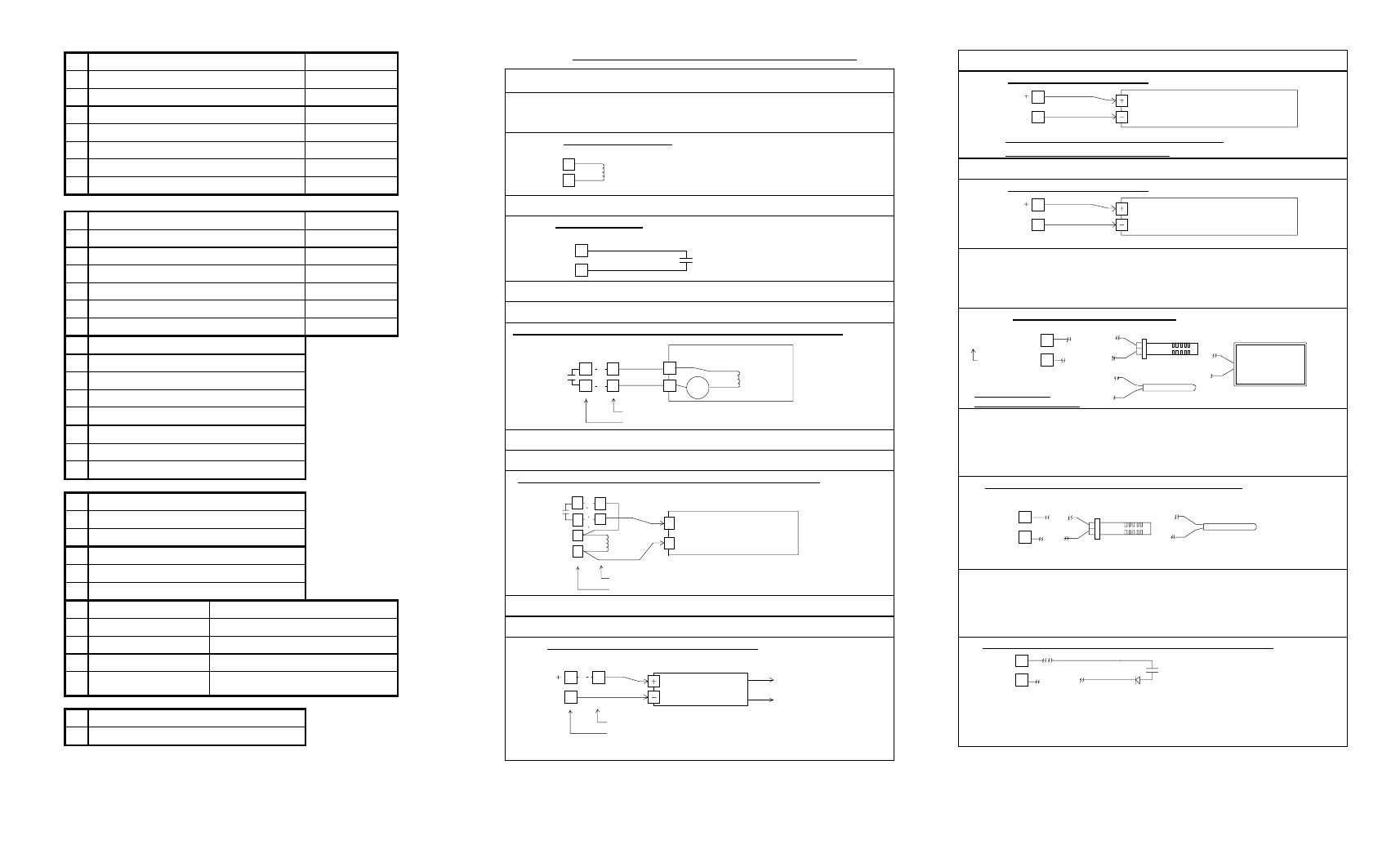
Output #3 Analog 0 to 10 Vdc
0 TO 10 VDC
COMMON
0 TO 10 Vdc
6
10
OUTPUT #3 USING 0 TO 10 Vdc
ELECTRONIC ACTUATOR, SCR,
OR VOLTAGE RELAY
Remote main temperature control sensor
Room or return control code D= 1,
Supply control code D=2
EXTERNAL
SENSOR
NOTE: REMOVE
INTERNAL J4 JUMPER
7
REMOTE MAIN CONTROL SENSOR
COMMON
6
VICONICS
DUCT S60 OR S70
ROOM S80
IMMERSION S90
Auto change over input.
1 supply sensor per thermostat
Automatic code G= 3
Automatic with recirculation code G= 4
AUTO CHANGE OVER INPUT WIRING: SUPPLY SENSOR
COMMON
INPUT
6
9
DUCT S60 OR S70
IMMERSION S90
NOTE: 1 SUPPLY SENSOR PER THERMOSTAT
Change over input. 1 dry contact for all
thermostat using the same transformer
Normally cooling code G= 1
Normally heating code G= 2
CLOSE = REVERSE
DAMPER OPERATION MODE
DIODE 1N4001
OR EQUIVALENT
COMMON
COMMON
INPUT
6
9
1 CONTACT FOR ALL THERMOSTAT
USING THE SAME TRANSFORMER
NOTE: IF 5 THERMOSTATS OR MORE ARE USED
ON THE SAME TRANSFOMER, INSTALL 1 DIODE
PER CHANGE OVER CONTACT
CHANGE OVER INPUT WIRING: CHANGE OVER THERMOSTAT