Viconics VT7000 Series PIR Application Guide User Manual
Page 10
10
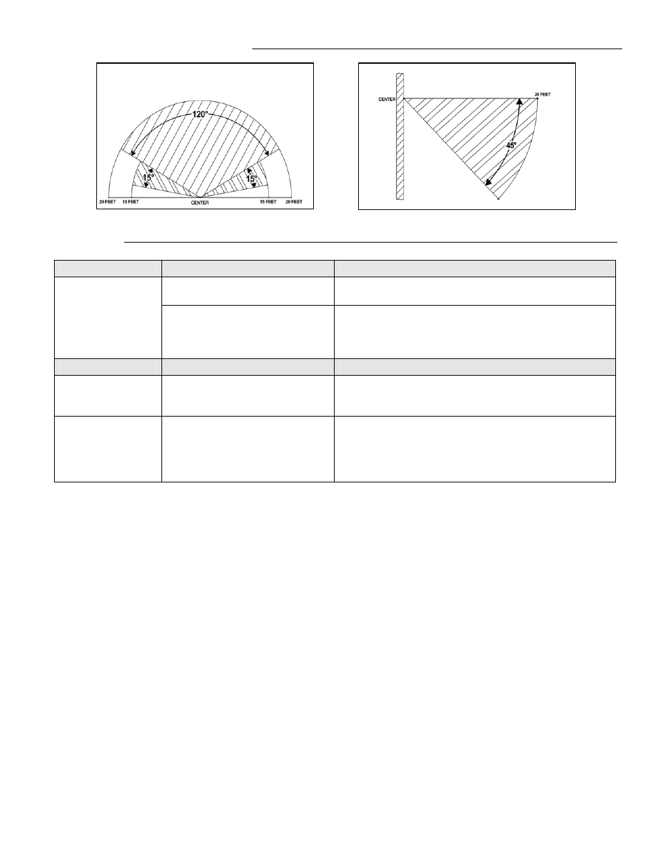
Typical Detection Pattern for VI-PIR Lens
Installation Tips
Tip Type
Area Of Interest
Explanation
PIR Connector
Polarized connector is located at bottom left hand corner
of VT7000 series thermostat
General Installation
Security Screw
A security screw has been provided in the thermostat
box. This screw should be carefully installed in the
intended mounting position located bottom center of
thermostat cover.
Tip Type
Area Of Interest
Explanation
Initial Power Up &
Commissioning
PIR Warm up period
PIR Sensor may take up-to 60 seconds after initial warm
up period to detect movement consistent with typical
detection pattern.
Visual indication (Status of PIR)
Visual indication of PIR activity for commissioning has
been provided via a blinking LEDs located on the
thermostat cover under the PIR lens. LEDs will be active
while occupant is in field of detection pattern for a period
of 30 minutes after initial power up.
Horizontal
Angle
(typical)
Vertical Angle
(typical)
- VTR8300 Line Voltage Application Guide (23 pages)
- VTR8300 Line Voltage Installation Guide (7 pages)
- VTR8300 Line Voltage User Interface Guide (32 pages)
- VC3000 Line Voltage Installation Guide (8 pages)
- VT8300 Low Voltage Installation Guide (13 pages)
- VT8300 Low Voltage Application Guide (64 pages)
- VT8300 Low Voltage User Interface Guide (45 pages)
- VT8000 Series Device Replacement Guide (7 pages)
- VT8600 Series BACnet Integration Guide (41 pages)
- VT8600 Installation Guide (12 pages)
- VT8600 User Interface Guide (47 pages)
- VT7657 BACnet Integration Guide (First Release 1000 Series) (23 pages)
- VT7657 BACnet Integration Guide (Current Release 5000 Series PIR Ready) (29 pages)
- VT7657 Echelon Integration Guide (22 pages)
- VT7657 Installation Manual (36 pages)
- VT7000 Series Installation Guide (2 pages)
- VT7000 Series Application Guide (27 pages)
- VT8000 Series Uploader Tool (5 pages)
- VT7600 Installation Guide (First Release 1000 Series) (24 pages)
- VT7600 Installation Guide (Current Release 5000 Series PIR Ready) (39 pages)
- VT7600 Echelon Integration Manual (22 pages)
- VT7000 Series PIR cover Installation Guide (2 pages)
- VT7682S Application Guide (17 pages)
- VT7682S Installation Manual (19 pages)
- VT7606E Installation Manual (34 pages)
- VT7600W Installation Manual (35 pages)
- VT7600F Installation Manual (29 pages)
- VT7300 Installation Manual (First Release 1000 Series) (17 pages)
- VT7300 Installation Manual (Previous Release 5000 Series PIR Ready) (17 pages)
- VT7300 Installation Manual (Current Release 5000 Series PIR Ready) (33 pages)
- VT7300 (BACnet) Integration Manual (31 pages)
- VT7300 (Echelon) Integration Manual (27 pages)
- VT7300F-2572 Installation Manual (26 pages)
- VT7200 Installation Manual (First Release 1000 Series) (15 pages)
- VT7200 Installation Manual (Previous Release 5000 Series PIR Ready) (15 pages)
- VT7200 Installation Manual (Current Release 5000 Series PIR Ready) (29 pages)
- VC3000 Installation Manual (10 pages)
- VTR7300 Installation Manual (25 pages)
- VTR7300 Application Manual (28 pages)
- VWA5000W Installation Guide (18 pages)
- VCM7000 Installation Guide (4 pages)
- VWZS Application Guide (40 pages)
- VWZS Integration Guide (70 pages)
- VWZS Engineering Guide Specifications (10 pages)