Viconics VT7000 Series Installation Guide User Manual
Page 2
2
INSTALLATION TIPS
Tip Type
Area Of Interest
Explanation
PIR Connector
Polarized connector is located at bottom left hand
corner of VT7000 series thermostat
General
Installation
Security Screw
A security screw has been provided in the thermostat
box. This screw should be carefully installed in the
intended mounting position located bottom center of
thermostat cover.
Tip Type
Area Of Interest
Explanation
Initial Power Up
&
Commissioning
PIR Warm up period
PIR Sensor may take up-to 60 seconds after initial
warm up period to detect movement consistent with
typical detection pattern.
Visual indication (Status of
PIR)
Visual indication of PIR activity for commissioning has
been provided via a blinking LEDs located on the
thermostat cover under the PIR lens. LEDs will be
active while occupant is in field of detection pattern for
a period of 30 minutes after initial power up.
VI-PIR COVER INSTALLATION
•
Remove security screw on the bottom of the current thermostat cover.
•
Open up by pulling on the bottom side of thermostat. (Fig. 3)
A) Identify current thermostat model type:
•
Use appropriate cover accessory part number as identified on the first page by referring to the thermostat
model number
•
The male polarized PIR connector is located at bottom left corner of thermostat (Fig. 4)
B) Installation:
•
Hinge new PIR thermostat cover into position (fig. 3).
•
Insert polarized connector into PIR female connector located on thermostat base (Fig 4 & 6)
•
Snap PIR thermostat cover into place and re-install the security screw (Fig 5)
•
Make appropriate parameter settings related to your application within the configuration menu as
identified in the thermostat installation
• Electronic controls are static sensitive devices. Discharge yourself properly
before manipulation and installing the thermostat and its accessories.
• Short circuit or wrong wiring may permanently damage the thermostat or the
equipment.
• All VT7000 series thermostats are to be used only as operating controls.
Whenever a control failure could lead to personal injury and/or loss of
property, it becomes the responsibility of the user to add safety devices and/or
alarm system to protect against such catastrophic failures.
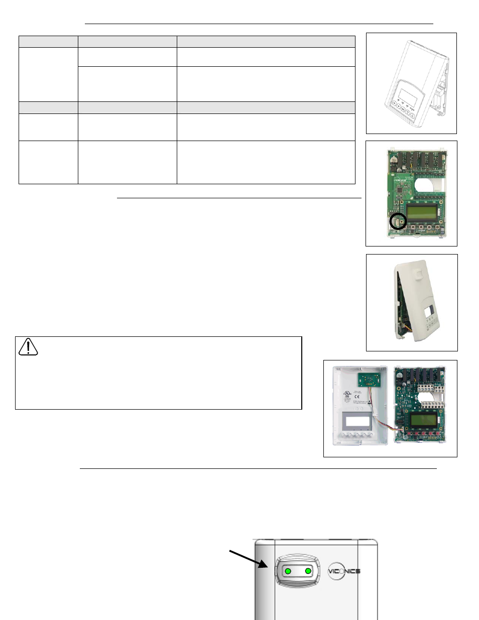
PIR STATUS LED’s
The PIR covers have 2 green status LEDs behind the PIR lens that can be used for diagnostic purposes during commissioning or servicing.
These LEDs are used to indicate a local movement detected by the PIR cover.
⇒ These status LEDs will only start to function to indicate movement 1 minute after the initial power up of the thermostat 24 Vac power
⇒ These status LEDs will stop to function to indicate movement 30 minutes after the initial power up of the thermostat 24 Vac power
LEDs location on PIR cover under the main sensor lens
Fig.5
Fig.4
Fig.3
Fig.6