Notes on operation, Operating mode display via led (only mpt 200), Notice – VACUUBRAND MPT 200 User Manual
Page 10
page 10 of 22
Documents are only to be used and distributed completely and unchanged. It is strictly the users´ responsibility to check carefully
the validity of this document with respect to his product. Manual-no.: 999226 // 05/05/2014
Notes on operation
(1)
➨
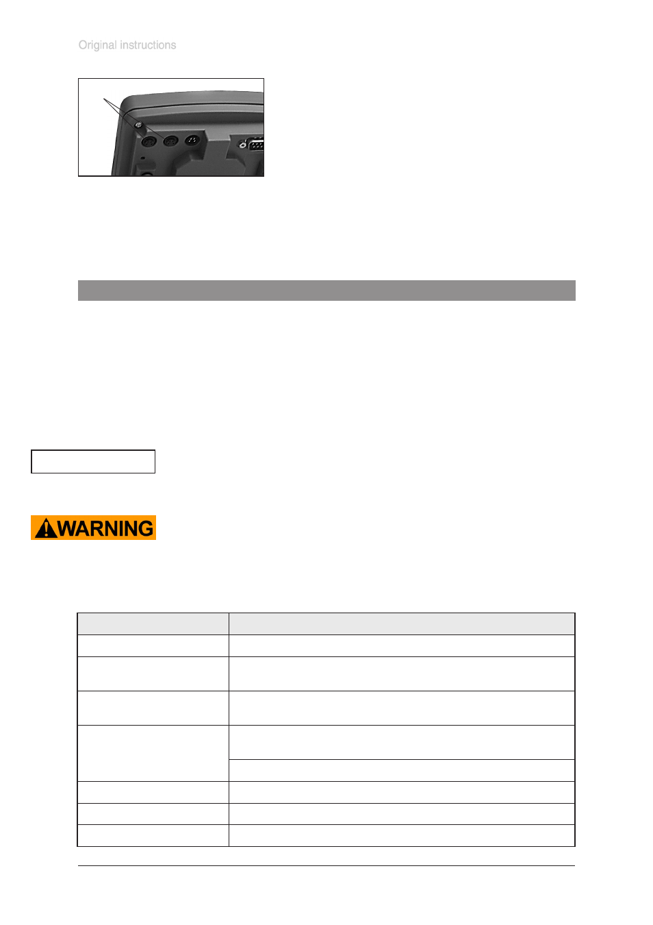
Connect the cable to the vacuum gauge head‘s serial in-
terface (MPT 100) or to its RS-485 socket (MPT 200) and
to one of the VACUU•BUS sockets (1) at the rear of the
vacuum gauge DCP 3000.
Attention: Do not cant when assembling or removing
plug connections! Comply with correct positioning of
the plug.
☞
Only connect/disconnect the cable to/from the vacuum
gauge head when it is off circuit. Separate the DCP 3000
from mains.
➨
Switch the DCP 3000 on.
When switching on the DCP 3000, a connected vacuum gauge head MPT 100 / MTP 200 is automati-
cally detected. The vacuum gauge head is displayed as active sensor in the status line of the vacuum
gauge as MPT 1. The pressure reading is indicated in exponential notation over the whole measuring
range.
Once all cables are connected, the vacuum gauge head MPT 100 / MPT 200 is ready to operate. Allow
the gauge head a stabilization time of approx. 5-10 minutes to meet its specifications. Even in case of
the vacuum gauge being switched off, the MPT 100 / MPT 200 stays ready for operation. To de-energize
the vacuum gauge head, unplug either its VACUU•BUS line or the power supply of the vacuum gauge.
The interior of the vacuum gauge head is highly sensitive! Do not insert fingers or
tools into the measuring chamber.
☞
The measured pressure is dependent on the gas type (see ”Notes on operation”).
Max. permitted pressure at the pressure transducer: 1.5 bar (absolute).
☞
Attention: Maximum pressure reading: 1*10
3
mbar. Pressure values above 1000
mbar are not displayed.
Risk of unnoticed overpressure. Risk of bursting!
NOTICE
Operating mode display via LED (only MPT 200)
Status of LED
Meaning
LED off
no or insufficient power supply
LED green on
valid measurement,
sensor component for low pressure range is active
LED green flashing
valid measurement,
sensor component for high pressure range is active
LED yellow on
unit function is O.K., but due to internal operations (e.g., during ad-
justment) no valid measuring values will be displayed temporarily
measuring range: overrange / underrange
LED red on
software or unit malfunction
LED green/yellow/red off (1s)
one-off: LED test after reset
LED red/green flashing
software update in progress