View of the disassembled pump head parts – VACUUBRAND RC 5 User Manual
Page 19
Documents are only to be used and distributed completely and unchanged. It is strictly the users´ responsibility to check carefully
the validity of this document with respect to his product. Manual-no.: 99 78 31 / 20/12/2006
page 19 of 28
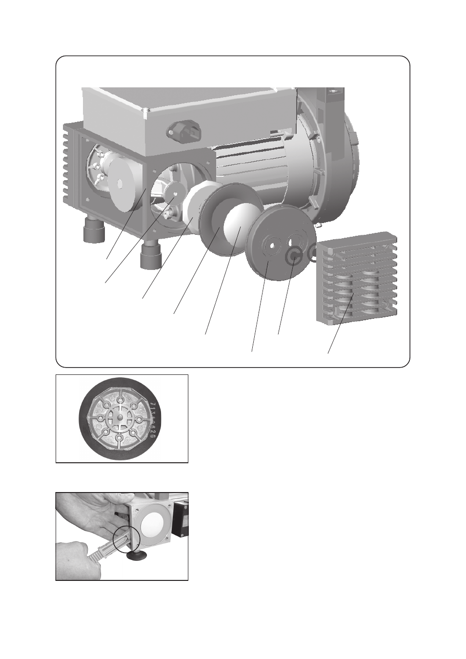
View of the disassembled pump head parts
diaphragm
housing cover
valve
head cover
diaphragm clamping disc
housing
rod
diaphragm support disc
➨ Position new diaphragm between diaphragm clamping disc
with square head screw and diaphragm support disc.
☞ Make sure that the square head screw of the diaphragm
clamping disc is correctly seated in the guide hole of the
diaphragm support disc.
☞ Note: Position diaphragm with white PTFE side to diaphragm
clamping disc (to pump chamber).
➨ Apply a drop of adhesive (OmniFit
®
50M or Loctite
®
243) to
thread of screw.
OmniFit
®
and Loctite
®
are registered trade marks of Henkel Technologies
➨ Use face wrench with torque indicator (recommended:
face wrench with torque indicator from VACUUBRAND,
Cat.-No.: 63 75 80) to assemble diaphragm clamping disc,
diaphragm and diaphragm support disc (and eventually
washers) to the connecting rod.
☞ Make sure that the square head screw of the diaphragm
clamping disc is correctly seated in the guide hole of the
diaphragm support disc.
Optimum torque for the diaphragm support disc: 6 Nm.
☞ The optimum torque is achieved if the pointer in the handle
of the VACUUBRAND face wrench shows to the longer mark-
ing line.