TruTrak Altrak VS User Manual
Page 8
TruTrak Flight System
6
Altrak Installation & User Guide
January 2009
8300-014 Rev B
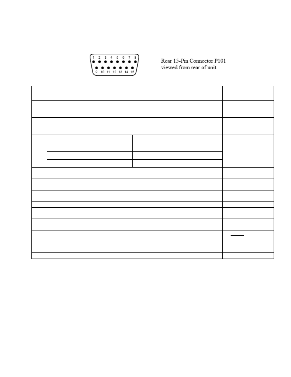
Electrical Pin-Out
The table below provides a brief explanation of each pin function on the main 15-pin connector P101.
P101
Pin
Function
Notes
1 Autopilot Master (+12 to +14 V DC). The autopilot itself draws less than 0.3 ampere.
Most of the current required by the system is used by the servo (up to 1Amp depending
on torque setting).
See note 3 on wiring
diagram
2 Control Wheel Switch. Connect as shown in wiring di
agram to a SPST momentary
switch
located remotely to the autopilot for convenient disengage function.
See note 3 on wiring
diagram
3 On / Off Switch. Connects to the illuminated push button module
4 Pitch Reverse Jumper,
present or absent, as follows:
Direction of the servo arm / capstan rotation
( as viewed from face of the servo body) for
UP
elevator
See note 2 on wiring
diagram
Pin 4 open ( no connection)
Servo CCW (counter-clockwise) → UP
Pin 4 Jumpered to pin 15
Servo CW (clockwise) → UP
5 Pitch Servo Trim Sensor. A signal from the pitch servo to the autopilot which indicates
an out-of-trim condition and its direction. (For use with trim sensing servo upgrade)
6 Engage Lamp / LED Connects to LED which connects to 470 ohm resistor.
See Module Rear View
on wiring diagram
7 Pitch Servo Torque Control. A signal from the autopilot to the pitch servo which sets
the amount of torque to be delivered by the servo.
8 VS control input from button assembly on panel.
VS Option only
9 AP On. Connect to pin 7 on Digitrak / Pictorial Pilot/Pictorial Pilot (This function is
only to be used if Altrak is coupled to Digitrak / Pictorial Pilot/Pictorial Pilot.)
See note 3 on wiring
diagram
10 Activity Select. Connect to ground for low activity, leave open for medium activity, and
connect to 12v for high activity
See note 4 on wiring
diagram
11
12
13
14
Pitch Servo control lines
. These lines cause the stepping motor in the pitch servo to run
in the appropriate direction at the desired velocity. They are small-signal lines and do not
have any substantial current-carrying capability or require any special shielding. Connect
to pitch servo as shown on wiring diagram.
Do NOT attempt to
reverse servo direction
by swapping wires
15 Ground Connection. Provide #20 AWG to common grounding point.