Analog – TRUE Systems P2 ANALOG User Manual
Page 14
P2
analog
OPERATION MANUAL
14
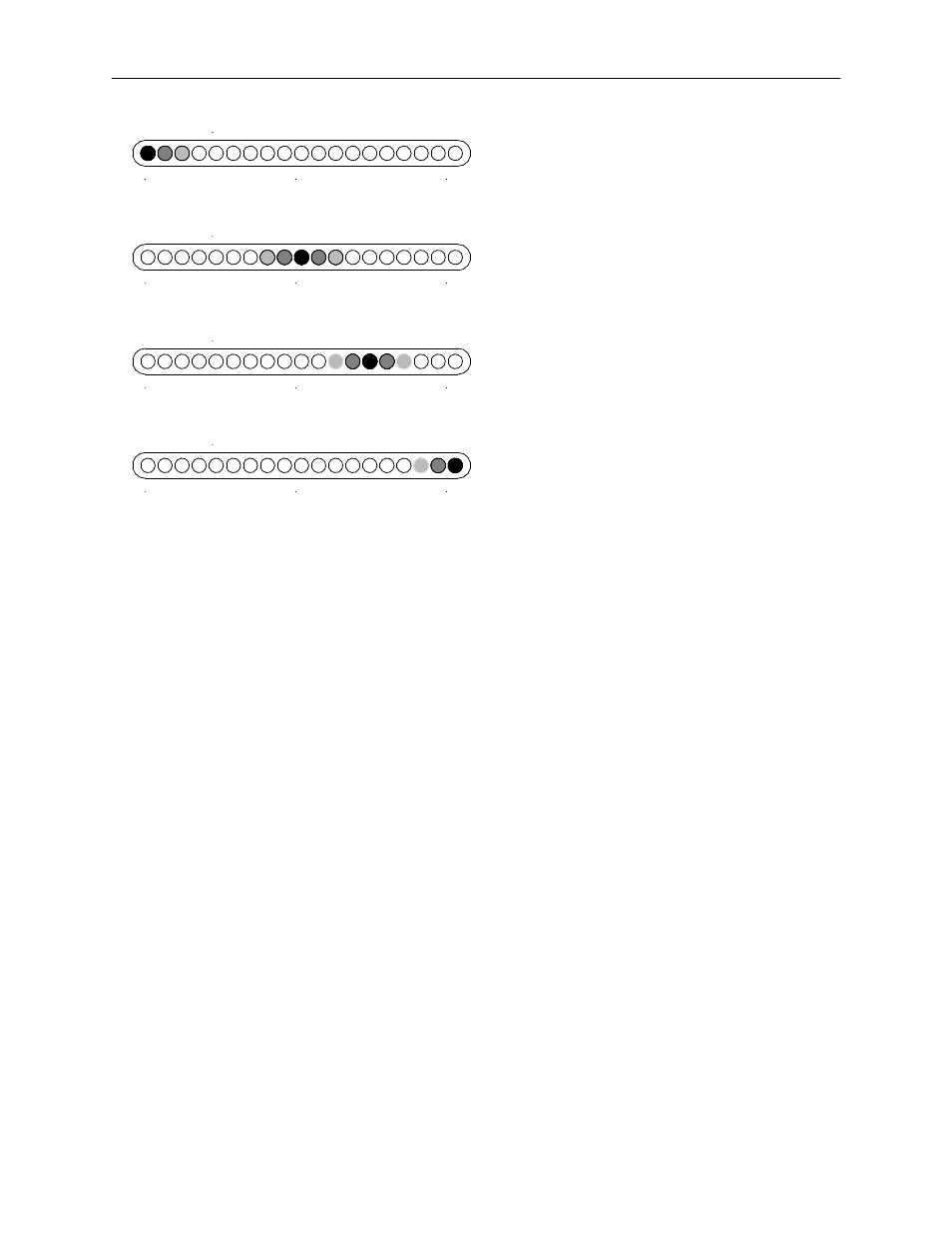
STEREO PHASE CORRELATION
0
90
180
STEREO PHASE CORRELATION
0
90
180
STEREO PHASE CORRELATION
0
90
180
STEREO PHASE CORRELATION
0
90
180
Output signals are essentially MONO
Typical STEREO display
Excessive PHASE ERRORS
(Adjust microphone)
POLARITY REVERSAL
(Reverse polarity on one microphone)
Here are some tips for using the Stereo Phase Correlation Display:
When attempting to get a good stereo image, position the mics so that most of the
Phase Display intensity is centered around the middle (yellow) range.
The Stereo Phase Correlation Display should not be thought of in the same way that
you think of a Level Indicator. In general, we don’
t want to see a RED Level Indicator
because it means we’
re going to get distortion. But, with the Phase Display, some
amount of “red activity” is normal when we have an acceptable stereo image. This
happens because there is a mix of various phase information in any complex audio
signal (music, voice). Conversely, an “all green” display is “safe” in that it shows
minimal out-of-phase information, but, for the same reason, the output signals will
not exhibit much of a stereo image.
You may want to become familiar with the Phase Display by observing its activity in
known situations. That is, situations where you know from experience that you have
good mic positioning and stereo image. Also, observe the Phase Display in
situations that you know will produce poor sonic outcome.
The Stereo Phase Correlation Display is intended for use with stereo mic placement
techniques. The Display may not provide meaningful information for independent,
two-channel applications.
When using the M-S mode it is unlikely that you will see a Polarity Reversal situation
as illustrated in the figure above. However, a right/left reversal may occur due to
wiring variations or reversed orientation of the SIDE mic. This can be corrected by
selecting 180
on Channel 2.