Analog – TRUE Systems P2 ANALOG User Manual
Page 10
P2
analog
OPERATION MANUAL
10
Our studio testing has shown that some of the more esoteric guitar/instrument
“super-cables” do, indeed, sound better. Noticeable improvement, but at a stiff price.
Try before you buy!
Avoid excessive cable length.
Replace damaged connectors.
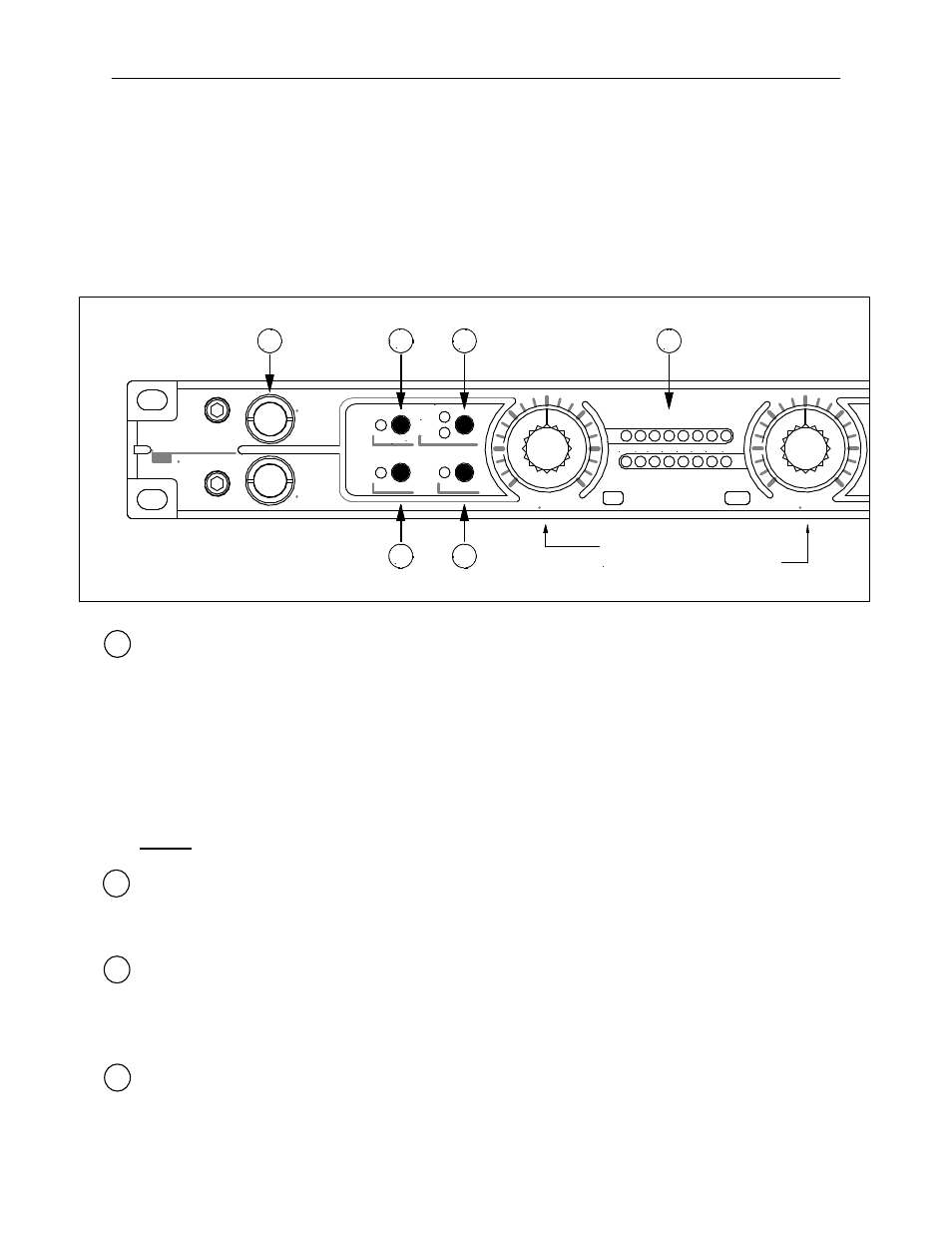
Front Panel Controls
1 DI-1 and/or DI-2 connectors are used to connect electric instrument pickups to
channel 1 or channel 2 of the
P2
analog
. Any microphones plugged into MIC1 or
MIC2 will be automatically de-selected. Direct inputs DI-1 and DI-2 are controlled by
gain controls for channels 1 and 2, respectively. Input selections for GAIN, HPF, and
Polarity (180
) apply to the DI inputs in the same manner as they apply to MIC
inputs. See below for explanation of these functions. The gain range for the direct
inputs is from -4 dB to +44 dB at normal gain (GAIN indicator ON) and -16 to +32dB
at low gain (GAIN indicator OFF).
NOTE: DO NOT use TRS plugs for these inputs as the DI will not function correctly.
2
Polarity reverse selector (180
). Input signal polarity is reversed when the 180
indicator is illuminated. Use this to reverse input polarity to correct for microphone
position or cable wiring differences.
3 High Pass Filter selector (HPF). Use this to reduce undesirable low frequency wind,
stage or handling noise. In general, the 40Hz setting is appropriate for musical
sources and the 80Hz setting is appropriate for voice. Note that use of the HPF will
most likely not eliminate the need for a pop screen for close-mic’
d vocals.
4 Gain range selector (GAIN). Use this to select the appropriate gain range. This
selector can be thought of as a “pad” although it does not have any sonic impact as
+24
SIG
+21
+18
+15
+12
+4
48V
HPF
GAIN
80HZ
40HZ
OL
1
2
DI-1
DI-2
T R U E
s y s tem s
180
o
1
2
3
MID
SIDE
In M-S Mode:
Gain 1 adjusts Mono signal level
Gain 2 adjusts Stereo image width
4
5
6