Toa VX-200PS ER User Manual
Page 8
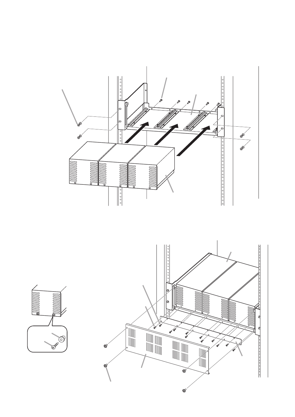
Screw
Spacer
Previous VX-200PS
8
Step 3. Fit the VX-2000PF's fixing bracket and front panel in place.
VX-2000PF's Front panel
VX-2000PF's
Fixing bracket
VX-200PS
Machine screw M3 x 6
(supplied with the VX-2000PF)
Self-tapping screw 4 x 10
(supplied with the VX-2000PF)
Self-tapping screw 4 x 10
(remove from the VX-200PS'
front panel)
Rack
3.2. Installing the VX-200PS Power Supply Unit in the VX-2000PF
To be compliant with EN 54-4, install the VX-2000DS and VX-2000PF in the CR cabinet rack series CR-15,
CR-22, CR-27, CR-35, CR-40, and CR-44.
Step 1. Mount the VX-2000PF in an equipment rack.
Step 2. Mount the VX-200PS in the VX-2000PF.
1
1
2
VX-200PS
Rack
VX-2000PF
Self-tapping screw 4 x 10
(remove from VX-200PS'
rear panel)
Supplied with the VX-2000PF
or other appropriate screw
Note
The VX-200PS units are slightly different in
specifications between the previous and current
production lots.
The previous unit has a spacer between the front
panel and screw. (See the figure below.)
In this case, use only the removed screws to fix
the VX-2000PF's Fixing bracket without using the
removed spacers.