Toa VX-200PS ER User Manual
Page 16
16
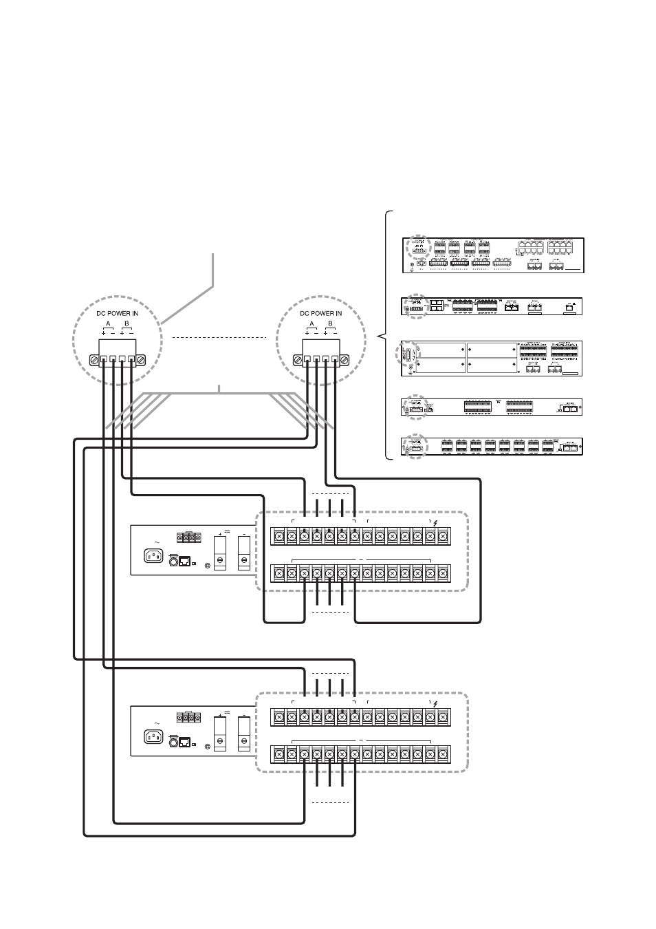
5.2. Connecting the VX-2000DS to SX-2000 System
[When using a redundant power system*]
In this connection example, 2 power supply units are used. Even if one of the 2 units fails or its power supply
line is broken, power is still supplied from the other unit, preventing the system from going down.
* A method of connecting separate power sources to each power input or connecting the commercial power
supply and backup power supply separately to each power input to prevent the system from going down
when a cable is broken or power fails.
24V
MAX150A
BATTERY POWER IN
( )
( )
( )
230V
50/60Hz 240W
6
1
5
4
3
2
6
1
5
4
3
2
DC POWER OUT (+) MAX 25A (DC 20V-40V)
PS IN (
+
) MAX 25A (DC20V-40V)
DS – SF
FUSE
LINK
THERMISTOR
1,2:PS1
PS IN
5,6:PS3
3,4:PS2
24V
MAX150A
BATTERY POWER IN
( )
( )
( )
230V
50/60Hz 240W
6
1
5
4
3
2
6
1
5
4
3
2
DC POWER OUT (+) MAX 25A (DC 20V-40V)
PS IN (
+
) MAX 25A (DC20V-40V)
DS – SF
FUSE
LINK
THERMISTOR
1,2:PS1
PS IN
5,6:PS3
3,4:PS2
SX-2100AI
SX-2100AO or SX-2000AO
(The figure below shows the SX-2100AO.)
Cable: AWG14 – 18
4P removable terminal plug
(supplied with the SX-2000SM, SX-2100AI, SX-2000AO
SX-2100AO, SX-2000CI, and SX-2000CO)
SX-2000SM
SX-2000CI
SX-2000CO
VX-2000DS
VX-2000DS
(DC power input terminal)
Power line A (–)
Power line A (+)
Power line B (–)
Power line B (+)
(DC power input terminal)
( )
6
1
5
4
3
2
6
1
5
4
3
2
DC POWER OUT (+) MAX 25A (DC 20V-40V)
PS IN (
+
) MAX 25A (DC20V-40V)
( )
6
1
5
4
3
2
6
1
5
4
3
2
DC POWER OUT (+) MAX 25A (DC 20V-40V)
PS IN (
+
) MAX 25A (DC20V-40V)