Nomenclature and functions – Toa WT-3800 User Manual
Page 4
4
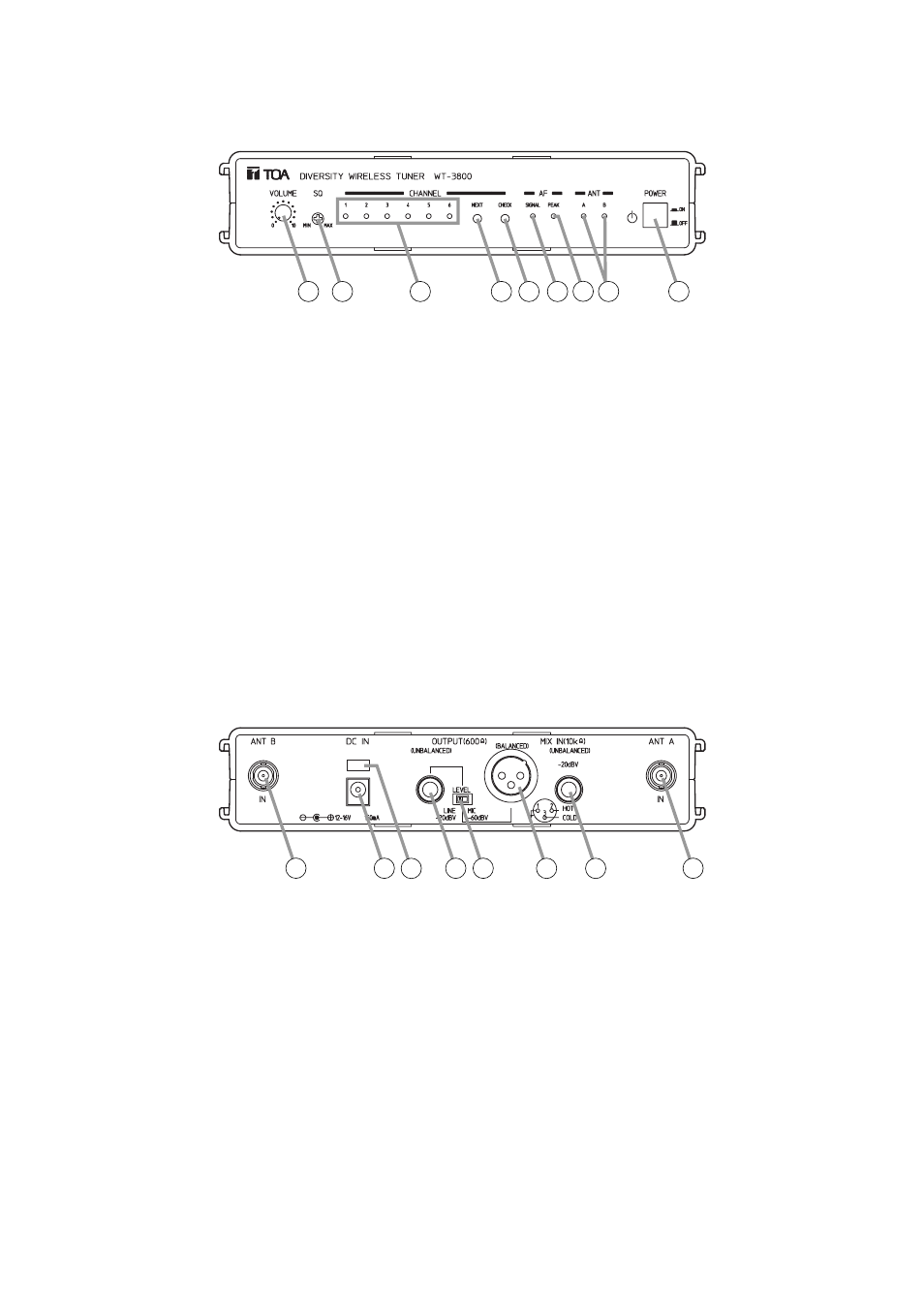
5. NOMENCLATURE AND FUNCTIONS
[Front]
[Rear]
1
2
3
4
5 6 7 8 9
10
10
11 12
13 14
15
16
1. Power switch
Press this switch to switch on the power, and
press this switch again to switch off the power.
2. Volume control
Controls an output level.
3. Squelch control
Controls a squelch level. Normally, set this control
to the "MIN" position.
4. Channel lamp
Indicates the selected channel.
5. Channel select key [NEXT]
Selects the frequency to receive.
6. Channel check key [CHECK]
Searches the "Idle channel" to be indicated by the
channel lamp (No.4).
7. AF signal lamp
Lights when the microphone input level reaches
the point of about 40 dB below the maximum
deviation.
8. AF peak lamp
Lights when the output level reaches the point of
about 3 dB below the clipping level.
9. Reception lamps
Either lamp, A or B, lights when the tuner receives
a radio signal.
10. Antenna input A, B
For signal routing. Input: 75
Ω, BNC
Connects to the supplied rod antenna or YW-3500.
For the wireless system covering a relatively
narrow area, use the supplied two rod antennas,
mounting each at a 45° angle outwards from a
vertical line.
11. DC input jack
Connect the DC power supply unit to this jack.
The input voltage is from 12 V to 16 V DC.
12. Cable hanger
Hook the power cable onto this part.
13. AF output
Unbalanced phone jack
14. AF output level selector
Selects the output level of either –60 dB/600
Ω
or –20 dB/600
Ω. (0 dB = 1 V)
15.AF output
Balanced XLR connector, male type
(Pin #2: Hot)
16. AF mixing input (Unbalanced)
Connects to other unit's AF output.
Input level: –20 dB, 4 k
Ω (0 dB = 1 V)