Installation – Toa RS-141 User Manual
Page 2
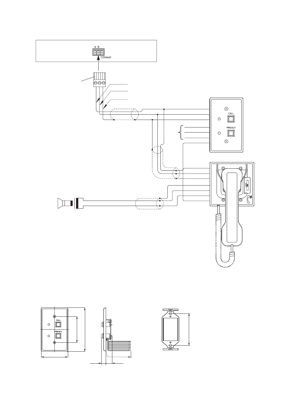
Substation interface unit
3P removable terminal plug
(supplied with the Substation
interface unit)
High-impedance speaker
(Impedance: 600 Ω or more)
Switch panel
(Figure shows the RS-140)
RS-141
N.C.
2-core shielded cable
2-core shielded cable
2-core shielded cable
Brown (A)
Red (B)
Orange (C)
Yellow (C+)
Green (B+)
Blue (A+)
Blue (COM)
Green (HOT)
Purple (H)
Brown (A)
Red (B)
Orange (C)
Yellow (C+)
Green (B+)
Blue (A+)
Purple (H)
Brown
Red
Orange
To the substation connection terminal
4. INSTALLATION
4.1. Switch Panel Installation
4.1.1. Dimensional diagram
[RS-140]
[Mounting bracket (Supplied with the RS-140/143/144)]
70
12.3
Unit: mm
16.3
200 or less
68.5
115
83.5
Note: The dimensions of RS-143 and RS-144 are the same as above.
Note
Cut out unused wires to avoid short-circuiting.
3.2. Switch Panel and Option Handset Connections