Toa N-8610RM User Manual
Page 4
4
4.2.2. RM-210
The RM-210 can be mounted on a wall using an optional WB-RM200 Wall-Mounting Bracket.
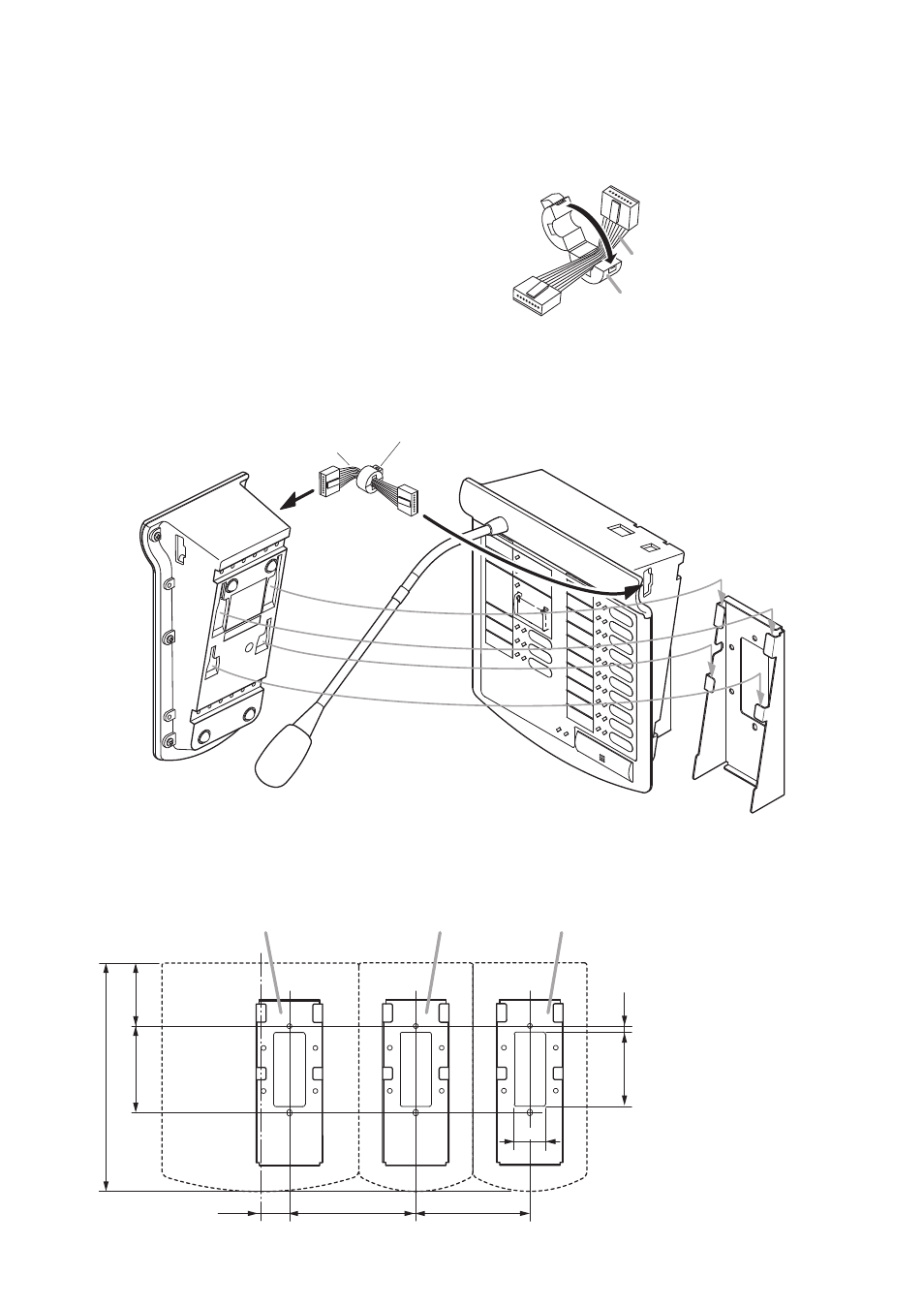
Step 1. Install the N-8610RM to the wall. (Refer to the previous page.)
Step 2. Install the WB-RM200 used for mounting the RM-210
to the wall.
Step 3. Connect between the RM-210 connection terminal
(EXTENSION) on the N-8610RM side and the RM
connection terminal (EXTENSION) on the RM-210 side
using the extension cable supplied with the RM-210.
In this case, install the ferrite clamp supplied with the
N-8610RM on the LAN cable as shown at right.
Step 4. Hook the bottom surface of the RM-210 onto the WB-RM200.
Tip
Follow the same procedures when linking additional
RM-210. But you need not install the ferrite clamp on the
extension cable used to connect between RM-210s.
N-8610RM
RM-210
2
1
Extension cable
(supplied with RM-210)
Ferrite clamp
(white, supplied with N-8610RM)
Wall mounting bracket
WB-RM200 (optional)
4
3
60.8
83.5
220.3
123
111
28
71.5
6
30
WB-RM200
(Necessary if one more RM-210 is added.)
N-8610RM
RM-210
RM-210
[WB-RM200 mounting dimensions]
WB-RM200 (optional)
WB-RM200 (optional)
Unit: mm
Extension cable
(supplied with RM-210)
Ferrite clamp
(white, supplied with N-8610RM)