Nomenclature and functions, Front, Rear – Toa N-8000MI User Manual
Page 8
8
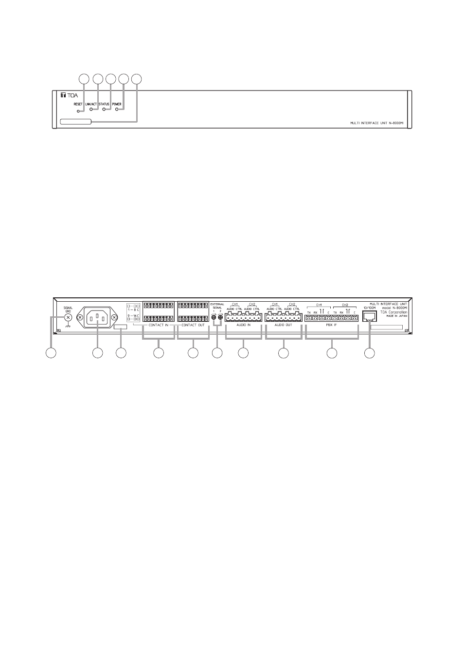
6. NOMENCLATURE AND FUNCTIONS
[Front]
1 2 3 4 5
00-05-F9-FF-00-00
[Rear]
6. Functional earth terminal [SIGNAL GND]
Be sure to ground this terminal unless the unit
connects to a PBX.
Note: This terminal is not for protective earth.
7. AC inlet
Connects the supplied power cord.
8. Cord clamp
Pass the power cord through this clamp to ensure
that the plug does not pull out when the unit is
mounted to a wall. (Refer to p. 11)
9. Contact input terminals [CONTACT IN]
No-voltage make contact inputs.
Short-circuit current: 10 mA, Open-circuit voltage:
12 V
10. Contact output terminals [CONTACT OUT]
Relay contact outputs.
Withstand voltage: 24 V DC, Control current:
Maximum 0.5 A
11.
Audio input level controls [ExTERNAL
SIGNAL 1, 2]
Use these controls to adjust the audio input
levels for channels 1 and 2 according to the input
sources.
12. Audio input terminal [AUDIO IN]
Includes audio inputs (maximum 0 dB*
2
, over 10
kΩ, balanced) and contact inputs (no-voltage
make contanct, short-circuit current: 10 mA,
open-circuit voltage: 12 V).
13. Audio output terminal [AUDIO OUT]
Includes audio outputs (maximum 0 dB*
2
, under
600 Ω, balanced) and control outputs (relay
contact withstand voltage: 24 V DC, control
current: maximum 0.5 A).
14. PBx interface terminal [PBx IF]
Connects to the Exchange of the EXES-2000
or EXES-6000 system by a tie-line, or the PBX
exchange via the OD (out-band-dialing) trunk.
15. Network connection terminal [10/100M]
Connects to a 10BASE-T- or 100BASE-TX-
compatible network. (Ethernet RJ45 jack)
*
2
0 dB = 1 V
1. Reset key [RESET]
Pressing this key reactivates the exchange.
2. LNK/ACT indicator [LNK/ACT] (Green)
Lights when connected to a network, and flashes
while transmitting or receiving data.
3. Status indicator [STATUS] (Red)
Continuously lights while data is written to an
internal storage medium (FlashMemory).
Flashes if there is a failure.
4. Power indicator [POWER] (Green)
Lights when power is supplied to the unit.
5. MAC address
This is the address*
1
used by the unit. Since the
relationship of each exchange location to its MAC
address is established when setting the network
attributes, keep track of this relationship for later
use.
*
1
The inherent address assigned to each network
component, expressed in 12-digit hexadecimal
notation.
M
E
M
E
6
7
8
9
10
11
12
13
14
15