Rear, Internal switch settings, Warning – Toa E-232 User Manual
Page 6
6
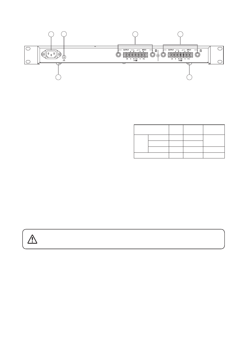
8. AC inlet
Connect this inlet to the wall outlet via the supplied
power cord.
9. Signal ground
Hum noise may be generated when external
equipment is connected to the unit .
Connecting this terminal to the signal ground
terminal of the external equipment may reduce
the hum noise.
Note
This ground is not for protective ground.
10. Input and output terminals
These terminals are of unbalanced type. Phone
jacks and screw terminals are connected in
parallel. When using the screw terminals, "H" is
hot and "E" is a grounding point.
11. Rubber feet (standard accessories)
Depending on the installation conditions, attach
the supplied rubber feet to the bottom of chassis.
(4 places)
7. INTERNAL SWITCH SETTINGS
This work should only be performed by a qualified professional
electrician. If users open the unit case or modify the unit, this may
cause fire or electric shock.
WARNING
The E-232 enables the following functions by setting the internal switches.
(1) Equalization range setting
Boost (amplification) or cut (attenuation) can be set for either 6 dB or 12 dB per channel.
(2) Ground loop cut [GND switch]
Depending on connected equipment, a ground loop that generates hum noise may be created. In such a case,
set the GND switch to "LIFT" position to cut the ground loop.
11
11
8
9
10
10
[Rear]
INPUT GAIN: +12
Rated
level
Maximum
level
Impedance
GAIN: 0
GAIN: –12
OUTPUT
* 0 dB = 0.775 Vrms
[Input/output specifications]
–8 dB
+4 dB
+16 dB
+4 dB
+8 dB
+20 dB
+32 dB
+20 dB
30 kΩ
12 kΩ
1 kΩ