38 operation, Others – StarTech.com IC485SEU User Manual
Page 4
3
8
Operation
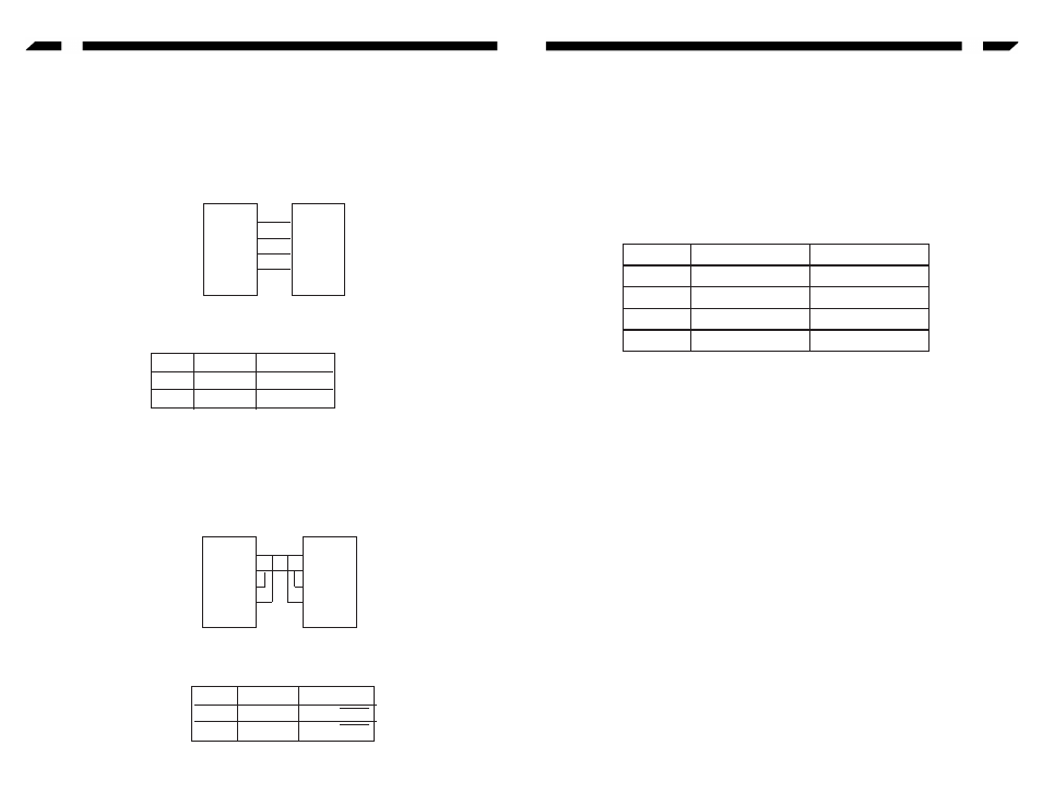
The IC485S / GB / EU supports 4 kinds of functions in 6 types of configurations.
Point-to-Point
Point-to-Point configuration means two devices that locate different places can be linked
together to communicate through a couple of IC485S / GB / EU devices.
If the PC1 is a DTE device, then the Device A SW1 should be set to DCE. If the PC1 is a
DCE device, the the Device A SW1 should be set to DTE. The switch setting method for
the Device be is identical to Device A’s.
Others
Terminal Block Definition
The four-screw terminal block has different definitions in different operation modes.
In the DCE/DTE mode, the terminal #1 (-V) and #2 (+V) are configured to transmit data,
the transmitter; the terminal #3 (+V) and #4 (-V) are configured to receive data,
the receiver,
In the
monitor mode, the terminals #1 and #2 are respectively the positive and negative
of receiver #1; the terminal #3 and #4 are the positive and negative of receiver #2.
Self Test
To test the internal circuit of the interface converter, connect a loop-back terminal to the
unit and process as follows:
1. Set SW1 to DCE (if the loop-back terminal is a DTE configuration).
2. Set SW2 to TxON, RxON.
3. Connect one wire from Tx-(#1) to Rx-(#4), and connect another wire from Tx+(#2)
to Rx+(#3).
4. Set the terminal to full duplex and enter data then the data should be displayed on
the screen.
5. If this occurs, the internal circuit is operational.
PC1
COM1/
COM2
T+
T-
R-
R+
IC485S
=>
A
PC2
COM1/
COM2
R+
R-
T-
T+
IC485S
=>
B
Device
A
B
SW1
DCE/DTE
DCE/DTE
SW2
TxON, RxON
TxON, RxON
Point-to-Point/4-Wire
Full Duplex
Configuration
PC1
COM1/
COM2
T+
T-
R-
R+
IC485S
=>
A
PC2
COM1/
COM2
R+
R-
T-
T+
IC485S
=>
B
Device
A
B
SW1
DCE/DTE
DCE/DTE
SW2
TxRTS, RxRTS
TxRTS, RxRTS
Point-to-Point/2-Wire
Half Duplex
Configuration
Pin #1
DCE/DTE
Monitor
1
Transmitter - V Receiver #1 - V
2
Transmitter + V Receiver #1 + V
3
Receiver + V
Receiver #2 + V
4
Receiver - V
Receiver #2 - V