StarTech.com IC485SEU User Manual
Page 3
9
2
Getting Started
This section is designed to help you prepare the IC485S / GB / EU for installation.
Please read through this section carefully before attempting to install the converter.
Unpacking the IC485S / GB / EU
This package should contain:
• 1 x interface converter
• 1 x power adapter
Installation
Before installing the IC485S / GB / EU you will need a 4-wire cable. This cable must go
from your location to the place you want to connect to.
1. Decide on one of the 6 possible configurations suitable for your application. Check the
Operation for the correct slide switch settings and phone wires connection, then
connect the IC485S / GB / EU to the PC.
2. Turn on the PCs.
3. Insert the adapter’s plug into the power jack on the right side of the converter.
4. Plug the power adapter into an AC outlet. The unit is not ready for operation.
Switch Function Description
Device Mode Selection
Position 1: DCE means that the IC485S / GB / EU is set to the DCE mode and must be
connected to a DTE device.
Position 2: DTE means that the IC485S / GB / EU is set to the DTE mode and it must be
connected to a DCE device.
Position 3: Monitor means that the IC485S / GB / EU is set to the monitor mode and it is
used to monitor the RS-485 line signals.
Transmitting and Receiving Mode Selection
Position 1: (TxON, RxON) means the IC485S / GB / EU is always in transmitting mode
and in receiving mode (using in Point-to-Point mode).
Position 2: (TxRTS, RxRTS) means the IC485S / GB / EU is in transmitting mode while
the RTS is at a high level and it is on receiving mode while the RTS signal is at a low
level (using in Multidrop mode).
Position 3: (TxRTS, RxON) means the IC485 / GB / EU is always in receiving mode and
it is in transmitting mode only while the RTS signal is at a high level (using in Multidrop
mode to monitor the RS/485 line signal).
Note: DTE means Data Terminal Equipment. DCE means Data Communication
Equipment. For more detailed information, refer to the Appendix.
Appendix
Troubleshooting
If failure of printing still exists upon the above solutions, please contact your dealer
for help.
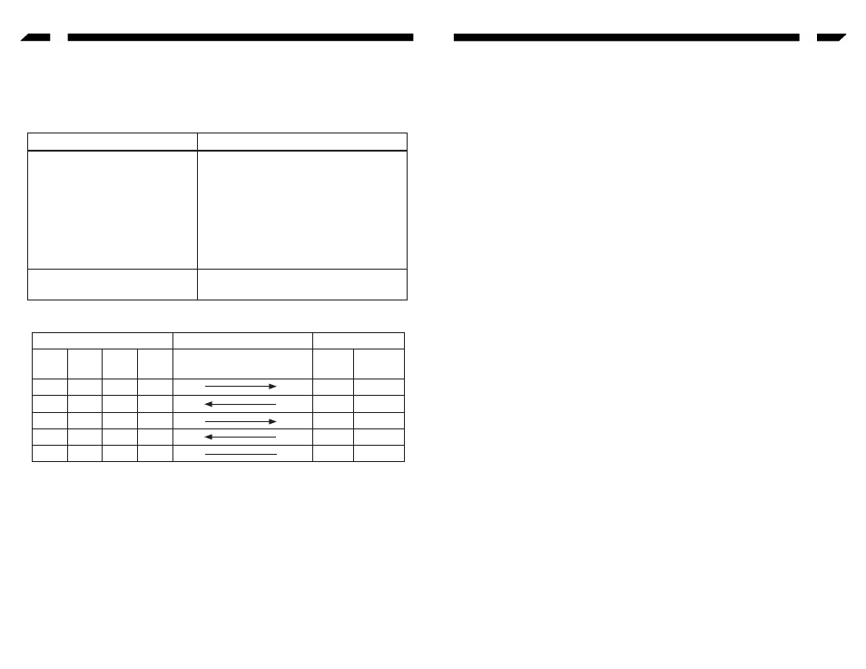
RS-232 DCE/DTE Description
Note: The DTE mode devices must be connected ti a DCE mode device because the
polarity of the communication signals are different. The shadow area is a connection
example for a DTE device to a DCE device.
Problem
Solution
Failure of Data Transmission
1. Check that the DC9V power adapter
is available.
2. Check that the IC485SEU is plugged
securely to the PC.
3. Check that the 4-wire cable is
connected properly at both ends.
4. Check that the SW1 and SW2 are
properly set.
Data Loss or Error
Check that the data rate and data format
are the same for both devices.
Device's Connector Pin #
Cables
IC485S/GB/EU
DCE
DB9
DTE
DB9
DCE
DB25
DTE
DB25
25/25 or
9/25-Pin
DCE
DB25
DTE
DB25
2
3
3
2
Tx Rx
3
2
3
2
2
3
Rx Tx
2
3
8
7
5
4
RTS CTS
5
4
7
8
4
5
CTS RTS
4
5
5
5
7
7
GND GND
7
7