Hardware installation – StarTech.com IES51000 User Manual
Page 9
Instruction Manual
6
Hardware Installation
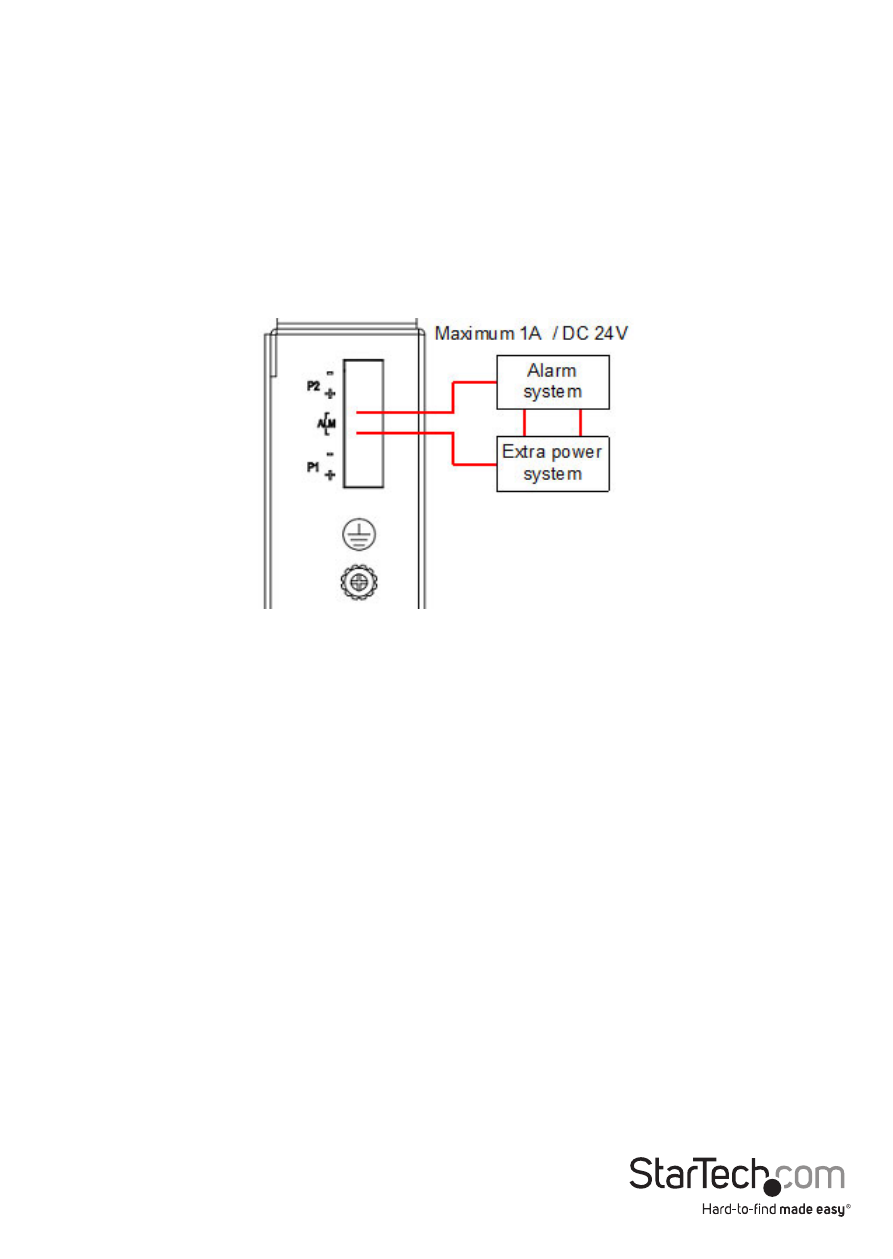
1. Ground the device using the ground screw.
2. Power the switch from a DC power supply (input range 12 – 58V) by connecting the
positive and negative wires into the V+ and V- contacts of P1 on the terminal block
and tightening the wire clamp screws.
3. (Optional) Connect a redundant power supply connection to the contacts for P2.
4. (Optional) Connect the alarm relay as shown. By inserting the wires and set the DIP
switch of the respective Port Alarm to “ON”, the relay output alarm will detect any
port failures, and form a short circuit. The alarm relay out is “Normally Open”.
5. Connect your uplink (connection to an upstream network switch) and network
devices using RJ45 terminated Cat 5 or better network cabling.
- MATRIX SV1654DX4I (72 pages)
- SV431UADVI (12 pages)
- SV231UADVI (10 pages)
- ENTERPRISE CLASS SV3253DXI (74 pages)
- STARVIEW SV830 (27 pages)
- DS254 (1 page)
- SV215MICUSBA (14 pages)
- SV215MICUSBA (13 pages)
- KVM SWITCHBOX VGA DS15H954 (1 page)
- SV221DVI (8 pages)
- StarView SV231 (14 pages)
- SV431DDUSB (12 pages)
- SV831SUN (16 pages)
- StarView SV431H (12 pages)
- DS154 (2 pages)
- ST4200MINI (8 pages)
- StarView SV231USB (15 pages)
- SV221DD (8 pages)
- ST4202USB (11 pages)
- DS15H54 (1 page)
- STARVIEW SV431DVIUAHR (16 pages)
- MSTDP123DP (10 pages)
- MSTMDP123DP (10 pages)
- DP2DVID2 (2 pages)
- DP2DVIS (2 pages)
- MDP2HDVGA (1 page)
- MDP2DPDVHD (2 pages)
- MDP2DVID (1 page)
- SLMPT2VGA (2 pages)
- SLMPT2HD (2 pages)
- DP2HDMIUSBA (2 pages)
- MDP2HDMIUSBA (2 pages)
- DP2DVID (2 pages)
- NOTECONS01 (18 pages)
- NOTECONS02 Quick Start (1 page)
- NOTECONS02 Manual (25 pages)
- SV231DD2DUA (14 pages)
- SV431DVIUDDM (12 pages)
- SV231DVIUDDM (10 pages)
- SV231USBDDM (12 pages)
- SV831DVIU (13 pages)
- SV231USB (13 pages)
- SV231DDVDUA (16 pages)
- SV431DUSBU (20 pages)
- SV831DUSBUK (17 pages)