Led indicators installation, Preparing your site – StarTech.com R300WN22MO5E User Manual
Page 7
Instruction Manual
2
1
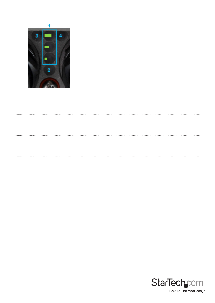
Wireless Signal
Strengths LEDs
Shows different signal strength levels. (Only supported in WDS,
Client Bridge + Repeater AP, CPE + Repeater AP Mode)
2
Power LED
A solid green light indicates the device is powered and ready.
3
LAN LED
A solid green light indicates the LAN port connection is OK. A
blinking green light indicates that the unit is transmitting data
over that port.
4
LAN LED (PoE)
A solid green light indicates the LAN port (PoE) connection is OK.
A blinking green light indicates that the unit is transmitting data
over that port
LED Indicators
Installation
Preparing Your Site
1. Determine the location for the included PoE injector and mount using the
appropriate screws/anchors for the material you are mounting to (not included).
2. Determine the location for the Wireless AP. If you are pole-mounting the AP, use
the included Pole Mounting Kit to secure the device. If you are wall mounting the
AP, use the appropriate screws/anchors for the material you are mounting to (not
included).
3. Prepare/purchase the required length of Ethernet cabling to go from the PoE
Injector to your LAN Switch or router, and from PoE Injector to the AP. The total
length of Ethernet cabling from the Wireless AP to your LAN switch or router should
not exceed 100m.
Note: Molded / Snagless Ethernet cables are not advised for this product, as the added
bulk on the connector end makes it difficult to fit within the included Cable Grommets.