Solberg BBF Assembly User Manual
Page 4
4
“BBF” Series Blower Base Frame Assembly Instructions Rev.: 9105
SOLBERG
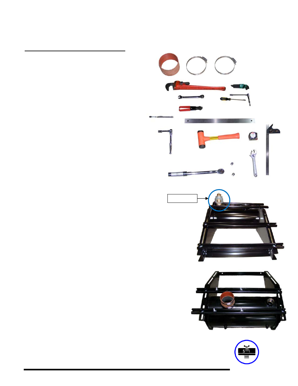
Customer or Solberg Supplied Parts (Boot Kits available separately upon request)
(1) Rubber sleeve/boot
(2) Band clamps
Helpful Tools:
-
Pipe
wrench
- Allen wrench set
- 3/4" Combination wrench
- Screwdriver (for band clamps)
- Compact bolt/wire cutter
- Tension measuring tool
-
Straight
edge
-
Lifting
hoist
- 3/8” Socket wrench
-
Soft
mallet
-
Tape
measure
- Torque wrench (w/ sockets)
-
Crescent
wrench
Solberg’s BBF Series, Blower Base Frame Assembly Instructions
1.1 Materials Needed (MN):
- (1) Solberg blower base frame
- (2) Standard channels
- (4) ½”-13 x 1-1/2” carriage bolts
- (4) ½”-13 “Whiz” flange nuts
1.2
If a relief valve is required, install into the relief port prior to affixing
the blower.
1.3 The frame is supplied with rails in place; slightly loosen rails for
necessary adjustments.
1.4 If frame needs rails installed, place (2) standard channels on top of
frame, the channels will overhang the frame on the right hand side.
Place (4) carriage bolts through square holes and thread on nuts
but do not tighten; rails need to be able to slide in frame slots.
2.1 MN - (1) Flex Coupling
- (2) Band Clamps
- (4) ½”-13 x 1-1/2” carriage bolts
2.2
Slide flex coupling over the OD of the BBF inlet pipe stub. Slide
band clamps over the OD of the flex coupling. Slide (4) carriage
bolts, (2) into each channel with the threaded portion protruding up
through the channel. These are for mounting the blower to the
channels.
Figure 1.2
Figure 2.2
Relief Valve