Slant/Fin EC-10DV Series User Manual
Page 4
4
EUTECTIC EC-10 DV
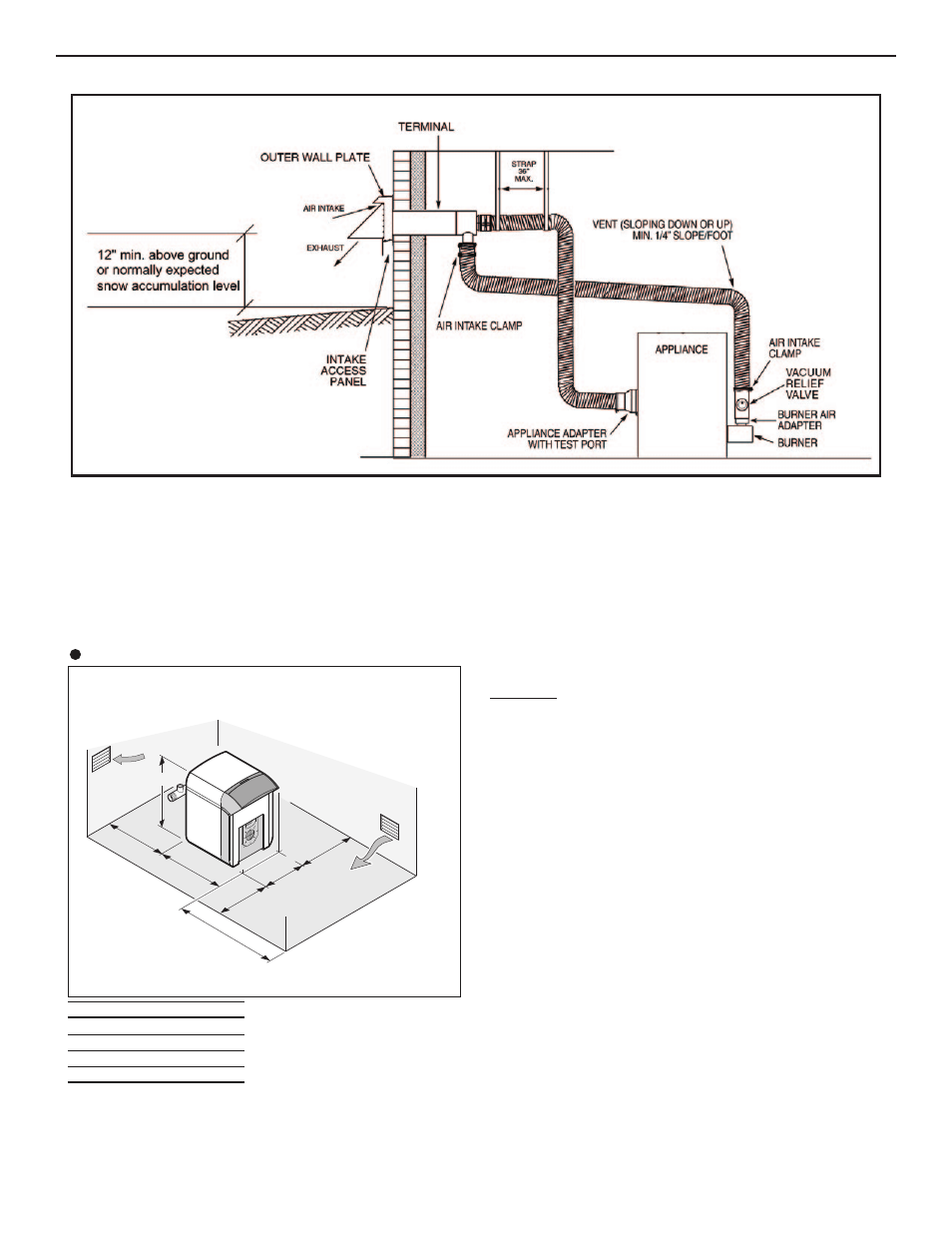
Sufficient space shall be left clear around the boiler.
The figures stated in inches in the drawings below are
the minimum recommended dimensions for providing
easy access around the boiler.
8578N016
20
A
40
22
7/1
6
20
20
33
7/8
Boiler A
(in)
EC-13DV
22
1/4
1/4
EC-14DV
27
EC-15DV
32
1/4
EC-16DV
37
1/4
EC-10DV
Do not stack items on or box in the appliance within
the required clearances to combustibles.
Figure 2. Typical Installation
PIPING
IMPORTANT:
Boilers are to be used with closed system. Any application that
uses water from system, causes the introduction of a frequent supply of fresh
water into the boiler. This will cause damage to the boiler. Use of heat
exchangers will prevent this damage.
PIPING FOR WATER UNITS
NOTE: On knock down boiler only, jacket may be installed after return piping
connection, but must be installed prior to adding trim & supply piping.
I. CIRCULATING SYSTEM
A.
FORCED CIRCULATION hot water heating system: Use the top
tapping as supply tapping, and use the rear bottom tappings for
the return.
B.
A FLOW CONTROL VALVE will prevent gravity circulation.
II. AIR CONTROL SYSTEMS
A.
DIAPHRAGM-TYPE COMPRESSION TANKS are used to control
system pressure in an AIR ELIMINATING SYSTEM: an automatic
air vent is used to REMOVE air from the system water. See figure 3.