Sigtronics EAI Operating Instructions User Manual
Page 6
We also do not recommend using screw type terminal strips
for intercom connections. There have been several instances
where terminal strips introduced high levels of electrical
noise like alternator whine into the intercom system. It is
acceptable however to tie the intercom red and green power
wires to existing vehicle terminal strips.
The best place to run the wiring between the unit and the
jack and PTT switches is out of sight. It should be run behind
vehicle panels and/or up in the headliner. This will reduce the
chance of personnel or equipment catching on or damag-
ing the wiring. Wire routing should take into account normal
vehicle operations. Wires should not interfere with any of the
vehicle’s controls, compartments, or doors. If the vehicle’s cab
tilts up for engine servicing, run wiring along the existing
vehicle wiring bundle. Make sure that wiring does not inter-
fere or restrict the tilting operation. Also, make sure that the
tilting operation will not cut or sever the wiring.
Make sure that the wiring does not rest on sharp edges. Over
time the vehicle’s vibration may cause a sharp edge to cut
into the wire. Use the provided wire grommets wherever
the four conductor wire goes through the hole into a jack
box. Use wire ties or tie wraps to secure and strain relieve
the wire.
At this time do not put the covers on the jack boxes or tighten
up the PTT switches. You will need to verify the correct opera-
tion of the system before you close everything up.
Power Connections:
The EAI unit will run on 11-34 VDC, so it automatically adjusts
to 12 or 24 volt vehicles. CAUTION: This EAI unit is designed
for negative ground vehicles only. It can be used on positive
ground vehicles only if a Sigtronics Positive Ground Adapter
is used. Contact your Sigtronics dealer on pricing and avail-
ability.
Make sure that the vehicle power is turned off before con-
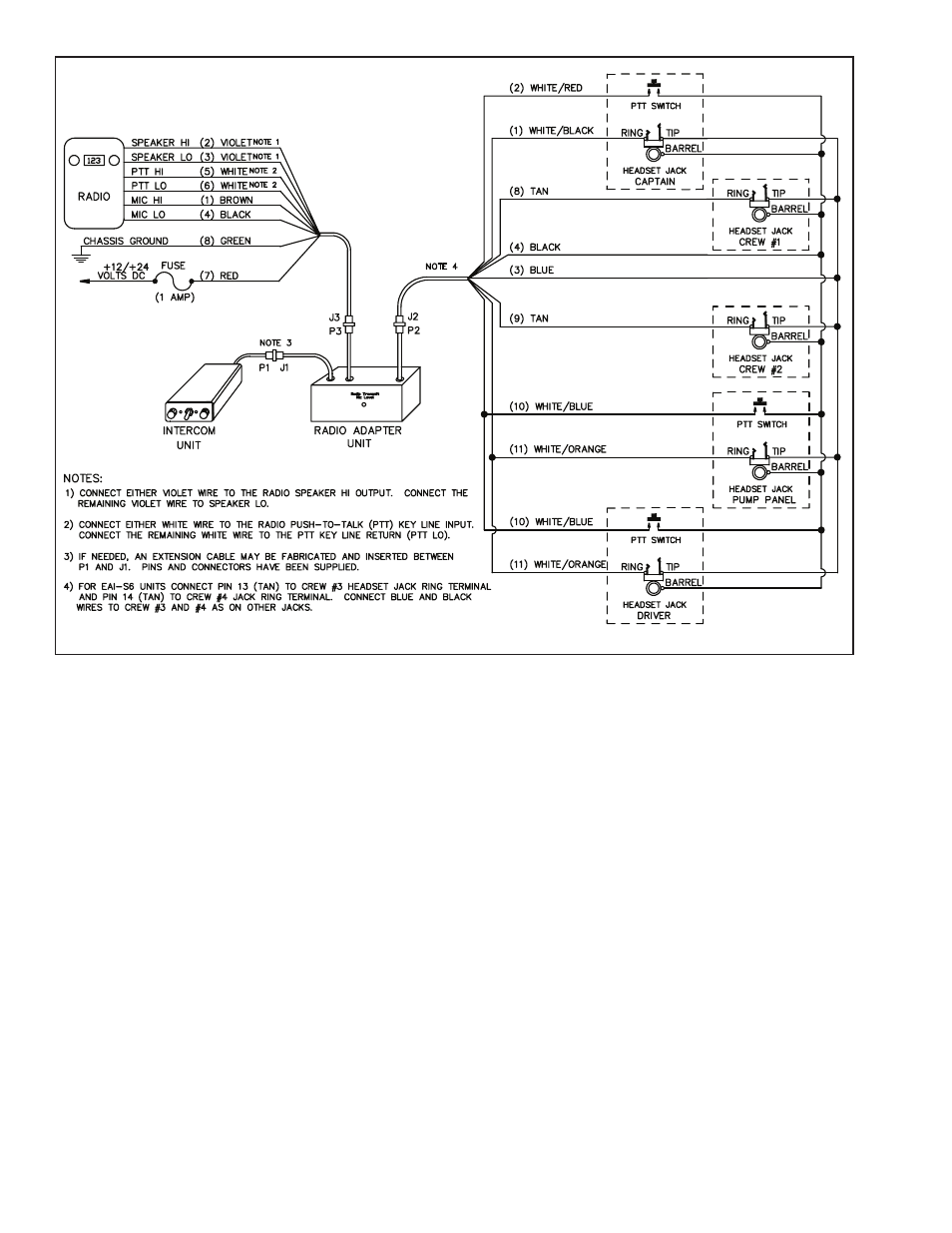
necting the EAI power wire. The power for the EAI units comes
in on the red and green wires on the Radio 1/ Power Interface
Cable. It is an eight wire cable with a 9 pin connector. Plug
the 9 pin connector J3 into the mating connector P3 on the
Radio Adapter unit.
Connect the red wire to vehicle power. (Try not to use a power
buss that also runs electrical motors such as fans or light bars
with rotating lights.) Connect the green wire to the vehicle
chassis ground.
INTERCOM WIRING CHECK OUT
System Setup:
Before you connect the vehicle’s radios, check out the system
operation. Do the following without the vehicle’s engine run-
ning:
First plug all headsets into the respective headset jacks.
6
������ �
������ � �� � ������ ����� � ������ �������