Figure 3 – Sigtronics EAI Operating Instructions User Manual
Page 5
2. Mount the jacks directly on the vehicle with a “through the
panel” mounting scheme. Advantages:
a) Smaller space requirement. (Only slightly larger than the
jack itself).
b) Only one hole to drill per jack (1/2 inch).
c) Most of jack is behind panel and out of the way.
Sigtronics recommends that you use the jack box mounting
method, but either approach can be used as well as a com-
bination of both.
If required, additional headset jacks, PTT switches, mounting
boxes, and hardware are available through your Sigtronics
dealer.
Splash Cover:
If a jack is to be mounted outside the vehicle (ie. on or near
a fire engines pump panel), a splash cover should be used
to keep excess moisture out of the jack when it is not in use.
Every EAI system comes with one such splash cover already
pre-mounted on a jack in a mounting box. On other positions,
where the headset is always plugged in, a splash cover is not
required.
Jack Box Mounting:
For most installations the wiring for the headset jack will
come out the back of the jack box. Four holes are provided in
the back of the box for mounting and headset jack wiring.
Place the jack box on the mounting surface and mark and
drill the corresponding holes into the vehicle. Use a 1/8 inch
drill for mounting holes, a 1/4 inch drill for the headset jack
wiring. Mount the jack box to the vehicle with the provided
#10 screws. The screws require a 5/16 inch hex driver.
Alternately, the headset jack wire can come out of the side of
the jack box if desired. You will have to drill the hole where
required. Use a 1/4 inch drill. Rubber wire grommets are pro-
vided for the wire going through the jack box hole.
Through the Panel Mounting:
For direct mounting of headset jacks on the vehicle panel you
will need to remove the jack from the jack box cover with a
1/2 inch wrench. For normal jack mounting (no splash cover),
the maximum panel thickness is 0.10 inches or a little less
than 1/8 of an inch. If you need the splash cover (optional), the
maximum panel thickness is 0.062 inches or 1/16 of an inch.
NOTE: Longer headset jacks that can accommodate thicker
panels are available from your Sigtronics dealer (order part
number 100418 - maximum panel thickness 0.155˝ with
splash cover and 0195˝ without).
Mounting on the panel requires that you insert the jack
from the back of the panel. Test jack(s) for clearance and fit.
Leave room behind - the jack expands when headset plug is
inserted. Make sure the back of the jack does not interfere
with any moving parts of the vehicle.
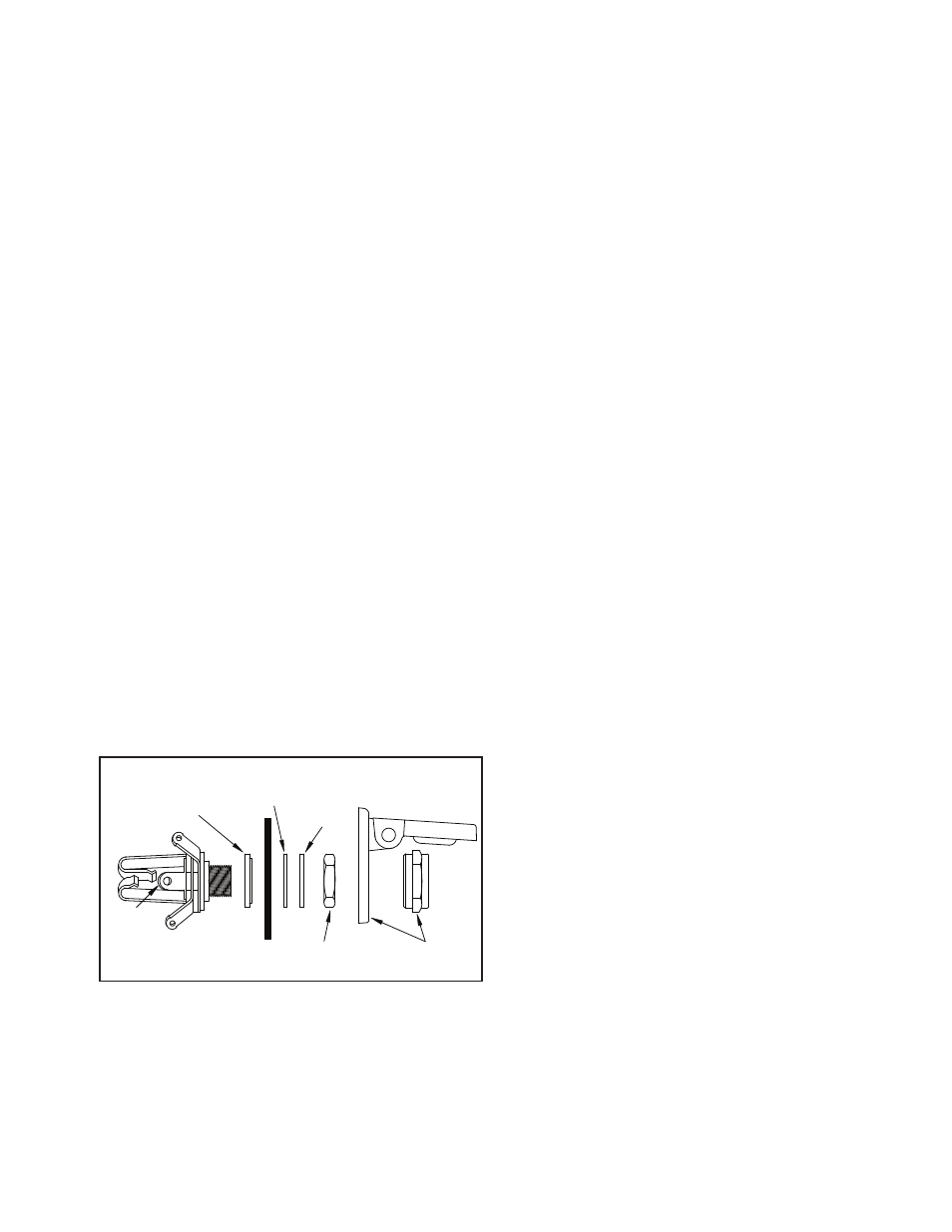
Drill a 1/2 inch hole in the panel. Install jack with mounting
washers and nut as in Figure 3. Both jack insulating washers
must be used. Jack has to be insulated from mounting spot
to minimize electrical noise getting into intercom system. No
need to tighten the jack now. You may have to remove the
jack to connect the wires.
PTT Switch Installation:
In order for the officers to transmit on their selected radios,
they will each need a Push-To-Talk (PU) switch.
The PTT switches should be placed within easy reach of the
users. It is also helpful if they can be easily seen by the users.
The maximum panel thickness that can accommodate the
switches is 3/16 of an inch. The PTT switches are mounted
through the panel from the front. They can also be mounted
in a jack box.
In the selected spot, drill a 5/8 inch hole. Mount the switch
into the hole but only loosely install the provided lock washer
and nut from the back. The PTT switch will likely have to be
removed to connect the wires later.
IV. HEADSET JACK AND PTT SWITCH WIRING
The wiring of the headset jacks and PTTs is straight forward.
In general, the 4 ft.. Headset Jack and PTT Switch Cable gets
wired to the four conductor Hook-up Wire (gray) and then the
Hook-up wire connects to the jacks and the PTT switches. For
the EAI-S4 and D4 models, this cable has a 12 pin connector
with 8 wires. For the EAI-S6 and D6, there is a 15 pin connector
and 10 wires. Before going on, plug in J2 of the cable into P2
on the Radio Adapter unit.
Flexible four conductor hook-up wire is provided with each
system to connect each headset jack and PTT switch to
the EAI unit’s Headset Jack and PTT Switch Cable. Enough
wire is provided for a typical vehicle installation. If required,
additional hook-up wire can be purchased through your
Sigtronics dealer.
Each headset jack requires three wires. Each PTT switch
requires two. If an officer’s PTT switch and headset jack are
mounted near each other, only four wires are needed. Refer
to the EAI Wiring Diagram (for EAI-S4 or EAI-S6 see Figure 4
on page 6 for EAI-D4 or EAI-D6 see Figure 5 on page 7) for the
exact wiring information.
The connections between the Headset Jack and PTT Switch
Cable and the hook-up wire should be soldered and insulated
for reliability. Do not use crimp type splices. They can become
intermittent over time. Use a good quality electrical tape, or
better yet, use heat shrink tubing to cover the soldered
connections. The connections to the headset jacks and PTT
switches will also have to be soldered. See Figure 3 on page
5 for jack terminal identification.
5
����
������
��������
����������
������
����
����������
������
����
�����
������
�������
�����
������� ����
���
��� �
��
� ������ ����� ��� ���
FIGURE 3