Control panel overview – Shellab SVAC2E-2 User Manual
Page 7
7
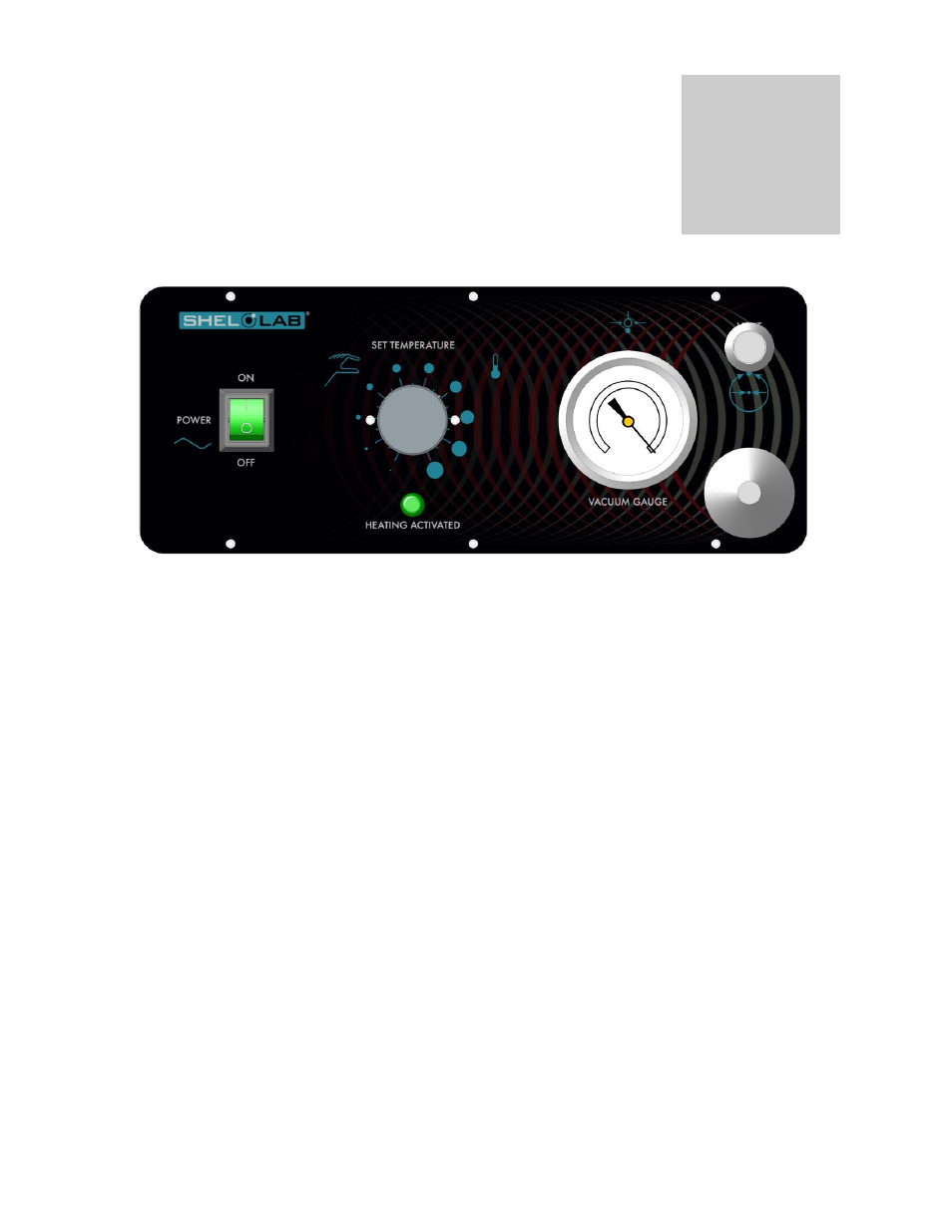
CONTROL PANEL OVERVIEW
4.1
POWER: The Main Power I/O (ON/OFF) switch controls all power to the oven. It must
be in the I, or ON position before any systems are operational.
4.2
HEATING ACTIVATED Light: This pilot lamp is on the when the temperature controller
has activated the heating elements to reach and maintain set point. During normal
operation this light will be on until the temperature in the chamber gets close to the
desired temperature and then will go off and on at regular intervals as the control
maintains the temperature within the chamber.
4.3
TEMPERATURE CONTROLLER: The controller is marked SET TEMPERATURE and is
equipped with an adjustment knob and a graduated dial. The graduated dial is marked
with 10 major increments and 9 minor increments. These increments can be used as
index points for setting and returning to set point temperatures.
4.4
VACUUM: The adjustment valve, located on the bottom right corner of the control panel,
allows opening and closing of the plumbing to an external vacuum pump or system.
Please note that the vacuum valve is the larger of the two valves on the control panel
and can be used to vacuum down the chamber. The valv
e is plumbed to the 3/8” tube
on the back of the unit
marked “Vacuum”.
4.5
VENT: This adjustment valve, located on the upper right corner of the control panel,
controls introduction of gas into the chamber there by relieving vacuum. This valve is
plumbed
to the ¼” tube in the back of the unit marked “Vent”.
4.6
VACUUM GAUGE: This component, mounted on the control panel adjacent to the two
valves, indicates the level of vacuum within the chamber. It has a dual scale and is
calibrated in “0 to 76 centimeters of mercury” and “0 to 30 inches of mercury”
Section
4