Controls overview, Controller keys and displays – Shellab SRI21FV-2 User Manual
Page 6
6
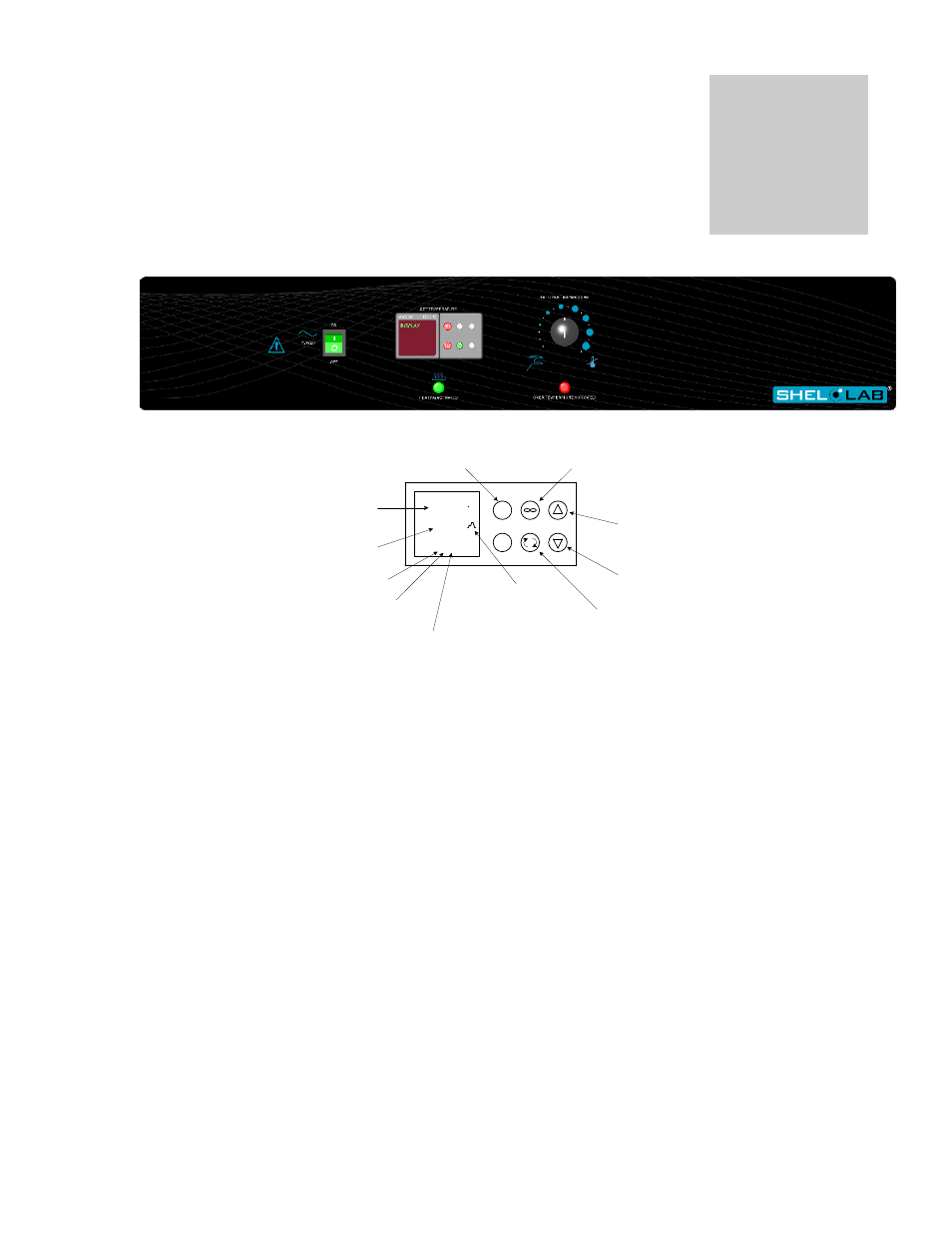
CONTROLS OVERVIEW
20.0
20.0
EZ1
EZ2
1 2 3
C
ACTUAL PROCESS
TEMPERATURE DISPLAY
PROCESS SETPOINT
DISPLAY
INDICATES OUTPUT 1 ACTIVE
HEATING ELEMENT ON
INDICATES OUTPUT 2
COOLING ACTIVE
INDICATES OUTPUT 3
ACTIVE LIGHTS ON
RAMPING SYMBOL
INDICATES PROGRAM
RUNNING WHEN ACTIVE
ADVANCE KEY
ALLOWS TO SCROLL
THROUGH PARAMETER LIST
DOWN ARROW KEY
ALLOWS TO LOWER SETPOINT
OR CHANGE PARAMETERS
UP ARROW KEY
ALLOWS TO RAISE SETPOINT
OR CHANGE PARAMETERS
INFINITE KEY
ALLOWS TO BACK UP
ONE LEVEL OR RETURN
TO HOME PAGE
EASY ZONE KEY 1
STARTS AND STOPS
PROGRAM
CONTROLLER KEYS AND DISPLAYS
4.1
Power Switch: The main power I/O (on/off) switch controls all power to the unit and must be in the I/ON
position before any systems are operational.
4.2
Main Temperature Control: The Main Temperature Control is a Watlow P.I.D. (Proportional Integral
Derivative) dual output control. We strongly recommend that all operators read the included Watlow manual
to become familiar with the control. This unit is specifically designed for drosophila applications and the
actual chamber temperature will fluctuate above and below setpoint. This is normal.
4.3
HEATING Light: This pilot lamp is ON when the unit is heating up to set point and is blinking when
controlling temperature at set point.
4.4
Overtemperature Thermostat: This controller is marked SET OVERTEMPERATURE and is equipped with
an adjustment knob and a graduated dial from 0 to 10. Completely independent of the Main Temperature
Controller, the Overtemperature Thermostat guards against any failure of the Main Temperature Controller
which would allow temperature to rise past set point. If temperature rises to the Overtemperature set point,
the Overtemperature Thermostat takes control of the heating element and allows continued use of the
incubator until the problem can be resolved, or service can be arranged. It is not recommended that the unit
be allowed to operate for an extended period of time using only the Thermostat as temperature uniformity
will suffer.
4.5
OVER TEMP Light: This pilot light comes on when the Overtemperature Thermostat has been activated.
Under normal operating conditions this light should never come on.
4.6
Low Limit Thermostat: Located on the lower right rear of the unit, the Low Limit Thermostat keeps the unit
from freezing. It is factory set to activate at 1
and disengage at 3
C and should not be adjusted.
4.7
Defrost Switch: Used to defrost the unit if frost should form. It is an ON/OFF switch located on the top
right, rear of the unit.
4.8
Fuse: Located on the back, bottom near the cord inlet. adjacent t the defrost switch in place of the circuit
breaker, the fuse offers protection against power source variations. Protection is in addition to the automatic
high temperature limit designed into the heating element. If the fuse is blown, the unit will shut down and the
cause should be determined and corrected before replacing the fuse.
Section
4