Adjustments – PS Engineering Tactical Radio Adapter User Manual
Page 8
PS Engineering
Radio Adapter (12100) Series Interface
Installation Manual
200-002-0002
2-4
Rev. 5, Feb. 2009
source, which will be connected to the aircraft microphone when the transceiver is select-
ed for transmit.
Transceivers with built-in speakers also do not provide sidetone, so VR2 can be adjusted
to cause sidetone to be present during transmission.
The audio input to the radio adapter (pin 6 hi, pin 19 low) is transformer isolated. In some
installations, it may be required to have a common ground to prevent loss of signal or dis-
tortion. In this case, connect pin 19 to pin 15.
2.4.4.1
Push to talk interface
The Radio Adapter is configurable for hi-seeking, low-seeking, or 2-pin contact push-to-
talk (PTT) systems.
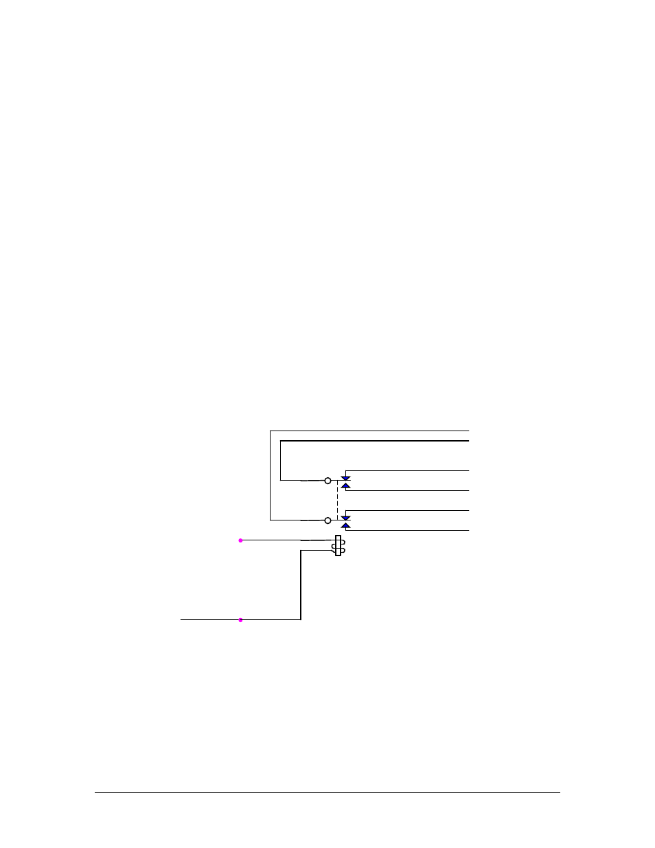
Pin 7 is the key-line input from the aircraft audio system. Grounding this line in PTT
causes a 2-pole relay to change states.
For instance, if the tactical radio has a ground seeking PTT line, you ground the common
#1of the relay, Pin 10, and connect the normally open connection, Pin 9 to the unit PTT
input. Keying the aircraft PTT then grounds Pin 9.
Connecting Pin 10 to logic high will pull Pin 9 high in PTT, and so on. If there are two
PTT contacts, one can be connected to common, and the other to NO.
10
22
24
9
12
11
+V
+
Pin 7
Connector
Pin
Figure 2 Mic Keying Relay Detail
2.5
Adjustments
The unit can be configured for several different interface combinations. Remove the
unit from its mounting bracket by removing the four screws at corners near the upper
edge.