Appendix b unit wiring, Figure 5-1 connector layout, Figure 6-1 installation diagram – PS Engineering Tactical Radio Adapter User Manual
Page 13
PS Engineering
Radio Adapter (12100) Series Interface
Installation Manual
200-002-0002
A
Rev. 5, Feb. 2009
Appendix A- Installation Information and Connector Layout
The Radio Adapter can be installed in any orientation in a convenient location. Mount the
unit using the flanges to a permanent aircraft structure, in accordance with AC 43.13-2B,
Acceptable Methods and Practices, Aircraft Alterations, Chapter 2, Radio Installations.
Relay 1 NC
Relay 1 NO
Ground
Audio Ground
Audio Ground
Relay 2 NO
Audio In Lo
Mic Audio Out Hi
Audio Out Lo
Audio Out Hi
No Connect
Relay 2 common
Relay 1 Common
Ground
Mic Audio In Lo
Aircraft Ground
Mic Audio In Hi
14 VDC
Relay 2 NC
Key Input
Audio In Hi
Mic Audio Out Lo
Aircraft Ground
28VDC
No Connect
13
25
12
11
24
23
10
22
21
20
19
9
8
7
6
18
17
16
15
14
5
4
3
2
1
Female Harness Connector
Figure 5-1 Connector Layout
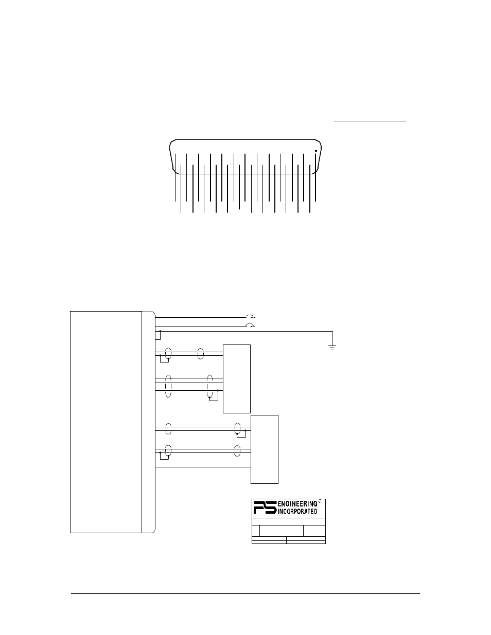
Appendix B Unit Wiring
1A
Aircraft Power 28 VDC
1
2
14
15
Sub-D DB-25 Male
Power In +28 VDC
Power In +14 VDC
Aircraft Ground
Aircraft Ground
Audio Out Hi
Audio Out Lo
4
17
REV
DATE:
ECO
SHEET OF
TITLE:
DOCUMENT NUMBER:
SIZE
Radio Adapter (12100) Interconnect
120-801-0002
2
02/24/2000
1
1
9800 MARTEL ROAD, LENOIR CITY TN 37772
1A
Aircraft Power 14 VDC
NOTES:
Mic Key
Mic Audio Hi
Mic Audio Lo
7
3
16
Aircraft Audio Panel
Mic Audio Hi
Mic Audio Lo
5
18
Audio In Hi
Audio In Lo
6
19
TAC Transceiver
Mic Key
10
22
9
12
24
11
Relay Common 1
NC 1
NO 1
Relay Common 2
NC 2
NO 2
1. All wire must conform to MIL-22759
or 27500. Minumum 24 gage
shielded wire.
2. Use 2- and 3-conductor with
shield as indicated.
3. Pin 7 controls the radio keying relay.
Refer to the radio information to
connect the proper configuration to
key the transmitter through the Adapter.
See Section 2.4.4.1.
4. Connect shields as shown.
5. Power is 14 or 28 VDC, as indicated.
6. If source or receive audio is transformer coupled,
and the audio is distorrted,
connect audio low to Pin 15.
Note 3
Note 3
NOTE 6
Figure 6-1 Installation Diagram