3 equipment installation procedures, 2 cable harness wiring, 1 electrical noise issues – PS Engineering PM1200 Installation Manual User Manual
Page 3
200-196-0104
Page 3
March 2013 Rev. 12
2.3
Equipment installation procedures
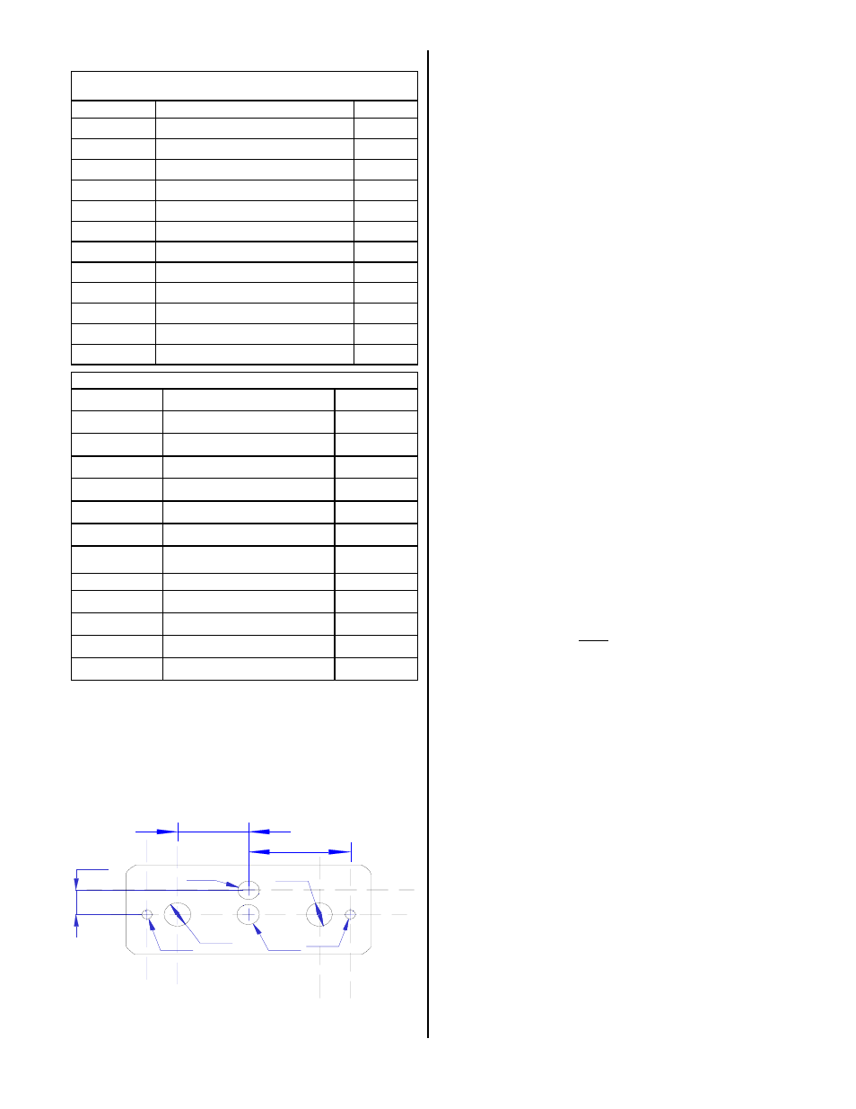
1.Using the template, drill six holes in the instrument panel
in a location convenient to the pilot position(s). The
intercom can be mounted horizontally or vertically with
supplied face plate.
2.Insert the PM1200 from behind the instrument panel,
aligning the holes for the knobs, LED, and switch.
3.Place the aluminum face-plate over the knob shafts and
secure, using the two # 4-40 round head screws pro-
vided.
4.Install the knobs over the volume and squelch control
shafts (except in the case of the 11961).
NOTE: See Page 9 for PM1200 Remote (11961R) instal-
lation diagram
2.2
Cable harness wiring
To complete the installation, a wire harness must be
made as shown in the appropriate diagram.
PS Engineering can make a custom-tailored wiring har-
ness for the installer. All harnesses use Mil-spec quality
components with professional techniques, and are fully
tested before shipment. Contact PS Engineering (865-988-
9800) for more information.
If the aircraft already has pilot and copilot headset jacks
installed, you may re-use them. Remove and discard all
wires from the copilot headset jacks. You may use the exist-
ing pilot headset jacks as the Auxiliary Aircraft Radio
Headset Jacks, but they should be moved to a new location
to avoid confusion with the pilot's headphone jacks. In the
event the intercom has to be removed for any reason, these
jacks provide access to the aircraft radio system.
To connect intercom into the aircraft audio system,
parallel the appropriate set of cables from the intercom to
the Auxiliary Aircraft Radio Headset Jacks. Finally, install
new headset jacks into the aircraft and connect them directly
to the appropriate pins of the PM1200. See the wiring dia-
gram for all details of the wire harness interconnects.
2.2.1 Electrical Noise Issues
WARNING: You must use separate shielded cables
for the microphone and headphone jacks. Combining these
two wires WILL cause loud oscillations and degrade the
intercom function. The oscillation is caused by the cross-
coupling between the large headphone signal and the small
microphone signal. The resulting feedback is a high-pitched
squeal that varies with the volume controls.
Due to the variety of the radio equipment found in to-
day's general aviation aircraft, there is the potential of both
radiated and conducted noise interference. The PM1200 has
a specially designed power supply to reduce conducted elec-
trical noise on the power bus of the aircraft by at least 50dB.
Although this is a very large amount of attenuation, it does
not eliminate all noise when the amount is excessive. There
must be at least 12 Volts DC present at the PM1200 for the
power supply to work within its designed regulation. Other-
wise, it will not be able to attenuate noise properly.
Shielding can protect the system from radiated noise
(rotating beacon, electric gyros, switching power supplies,
etc.). However, installation combinations can occur where
minor interference is possible. The PM1200 was designed
in an interference -protected chassis and has internal filter
capacitors on all input lines.
Ground loop noise occurs when there are two different
0.320
Ш0.125
Ш0.313
Ш0.313
Ш0.125
Ш0.265
Ш0.25
0.840
1.200
Dimensions in inches
PM1200 Hole spacing (Not to scale)
Part Number
Description
Quantity
475-442-0002
#4-40 Machine screws, black
2
625-003-0001
Soft Touch knobs
2
425-025-0009
25 pin Sub-d connector shell
1
625-025-0001
Connector hood
1
575-120-0001
Reversible aluminum face plate
1
250-000-0002
2-place jack kit
1
200-196-00XX
Operator's and Installation Manual
1
122-102-0001
Drill Template
1
PM1200 Standard and Expansion
(11960 & 11960-Exp) Installation Kit P/N 250-120-0100
475-002-0002
Thumbscrews
2
425-020-5089
Crimp Pins (Male)
25
350-990-0015
Foam Mic Muff
2
350-9909-0001
Leather Mic cover
2
PM1200 Remote (11961) Installation Kit P/N 250-120-0200
Part Number
Description
Quantity
350-990-0015
Foam Mic Muff
2
350-9909-0001
Leather Mic cover
2
425-025-0009
25 pin Sub-d connector sell
1
625-025-0001
Connector hood
1
425-0205089
Crimp Pins (Male)
25
250-000-0002
2-place jack kit
1
200-196-00XX
Operator's and Installation Manual
1
675-020-0103
Copilot volume pot ¼” shaft
1
731-001-0001
Switch, SPDT On-On
2
625-020-0005
Knob, Black 1/2” shaft
2
475-002-0002
Thumbscrews
2
675-120-0103
Pilot volume pot w/Switch ¼” shaft
1