Appendix d wiring informat, Ps engineering – PS Engineering PM2CREW User Manual
Page 9
PS Engineering
PM2Crew Expansion module (11918)
200-004-0004 Page
B
Rev. 4, Sept. 2000
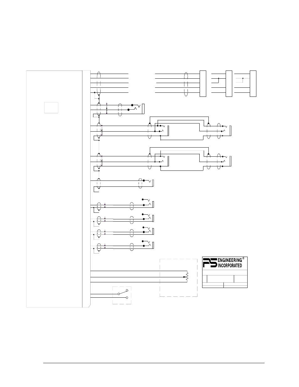
Appendix D Wiring Informat
ion
1
2
15
3
14
PM2CREW (11918) Female Sub-D DB-25
Pass 1 Mic
Expansion Power In
Expansion Audio In (R)
Expansion Audio In (L)
Expansion Audio Output
Expansion Ground
Pass #1
Pass 1 Mic Audio Hi
Pass 1 Mic Audio Lo
16
4
Pass 2 Mic
Pass 2 Mic Audio Hi
Pass 2 Mic Audio Lo
17
5
9800 MARTEL ROAD, LENOIR CITY TN 37772
1
1
03/08/00
1
120-118-0000
PM2CREW (11918) WIRING DIAGRAM
SIZE DOCUMENT NUMBER:
TITLE:
SHEET OF
ECO
DATE:
REV
1. All wire must conform to MIL-22759
or 27500. Minumum 24 gage shielded wire.
2. Use 2-, 3-, and 4-conductor with shield
as indicated.
3. Use insulating washers on all jacks. Jacks
must be electrically floating.
4. Connect shields at intercom end only
5. Consult main unit Installation manual for
remaining installation information.
6. DO NOT CONNECT more than one entertainment inp
for PMA4000. The PMA4000 music input feeds
the expansion unit. Therefore, if music is presented to
the PMA4000 it will also be present in ine expansion un
If music is desired in the expansion unit ONLY, leave th
PMA4000 unit open, and connect to PM2CREW.
NOTES:
17
4
5
3
Expansion Ground
Audio to Main Unit
Audio (right) from Main Unit
Expansion Power
25
13
Music (L)
Music (R)
Entertainment Input
(NOTE 6)
Pass #2 Headphones
Pass 1 & 3 Phones (L) Hi
Pass 1 & 3 Phones (R) Hi
Headphone Lo
8
20
Pass # 3
Pass 2 & 4 Phones (L) Hi
Pass 2 & 4 Phones (R) Hi
Headphone Lo
9
21
Pass # 4 Headphones
Pass 3 Mic
Pass 3 Mic Audio Hi
Pass 3 Mic Audio Lo
18
6
Pass 4 Mic
Pass 4 Mic Audio Hi
Pass 4 Mic Audio Lo
19
7
Mono Aux Input
(tape recorder, etc)
Mono Aux input
22
10
23
11
Sq. Pot Outside Tab
Sq. Pot Center Tab
Sq. Pot Outside Tab
Soft Mute
Inhibit
(Switch not included)
Remote Squelch
Potentiometer
(11918R & 11918R6 only)
Inhibit Switch 2
Inhibit Switch 1
24
12
PMA4000
Bottom Connector
See unit Installation manual
for complete information
NOTE
6
15
16
3
2
PM1000
Series
17
5
18
4
1
PM2000
Series
Audio (left) from Main Unit
P/N 675-020-0103
1
2
3
PM2CREW (11918, 11918R) Wiring