1 general information, 2 unpacking and preliminary inspection, 3 equipment installation procedures – PS Engineering PM2CREW User Manual
Page 4
PS Engineering
PM2Crew Expansion module (11918)
200-004-0004 Page
2-1
Rev. 4, Sept. 2000
Section 2 Installation
2.1 General
Information
The PM2CREW comes with all necessary hardware for a typical installation. The unit is installed either in
the panel (11918) or mounted blindly (11918R). If panel mounted, it can be installed near the audio panel,
or a panel near the passengers. If blind mounted, it can be mounted nearly anywhere. If blind mounted, the
squelch control should be mounted in a location convenient to the passengers. The 11918R volume control
for the passengers is factory set for a balanced output, but can be field adjusted through the holes in the
side of the unit.
Installation of the PM2CREW, using the available wiring and hardware supplied, does not require special
tools or knowledge other than described in FAA Advisory Circular 43.13-2. It is the installer's
responsibility to determine the approval basis for this installation. A FAA Form 337, or other approval may
be required. See Appendix B for example of FAA Form 337.
2.2
Unpacking and preliminary inspection
The PM2CREW was carefully inspected mechanically and thoroughly tested electronically before
shipment. It should be free of electrical or cosmetic defect.
Upon receipt, verify that the parts kit includes the following:
PM2CREW Installation Kits
Part Number
Description
11918
Quantity
11918P6
Quantit
y
11918R
Quantit
y
11918R
6
Quantit
y
11918R
Quantit
y
11918R
6
Quantit
y
475-440-0318 #4-40
Machine
screws,
black
4 4 4 4 4 4
625-002-0002 Knobs
2 2 2 2 2 2
425-025-0002
25 pin Sub-d male connector
1
1
1
1
1
1
425-025-0003 Connector
hood
1 1 1 1 1 1
430-001-0001 Aluminum
face
plate
1 1 1 1 1 1
430-002-002 PM2CREW
Label
1 1 1 1 1 1
250-009-0002
Remote Squelch Installation
kit
1 1 1
200-004-0004 Operator's
and
Installation
Manual
1 1 1 1 1 1
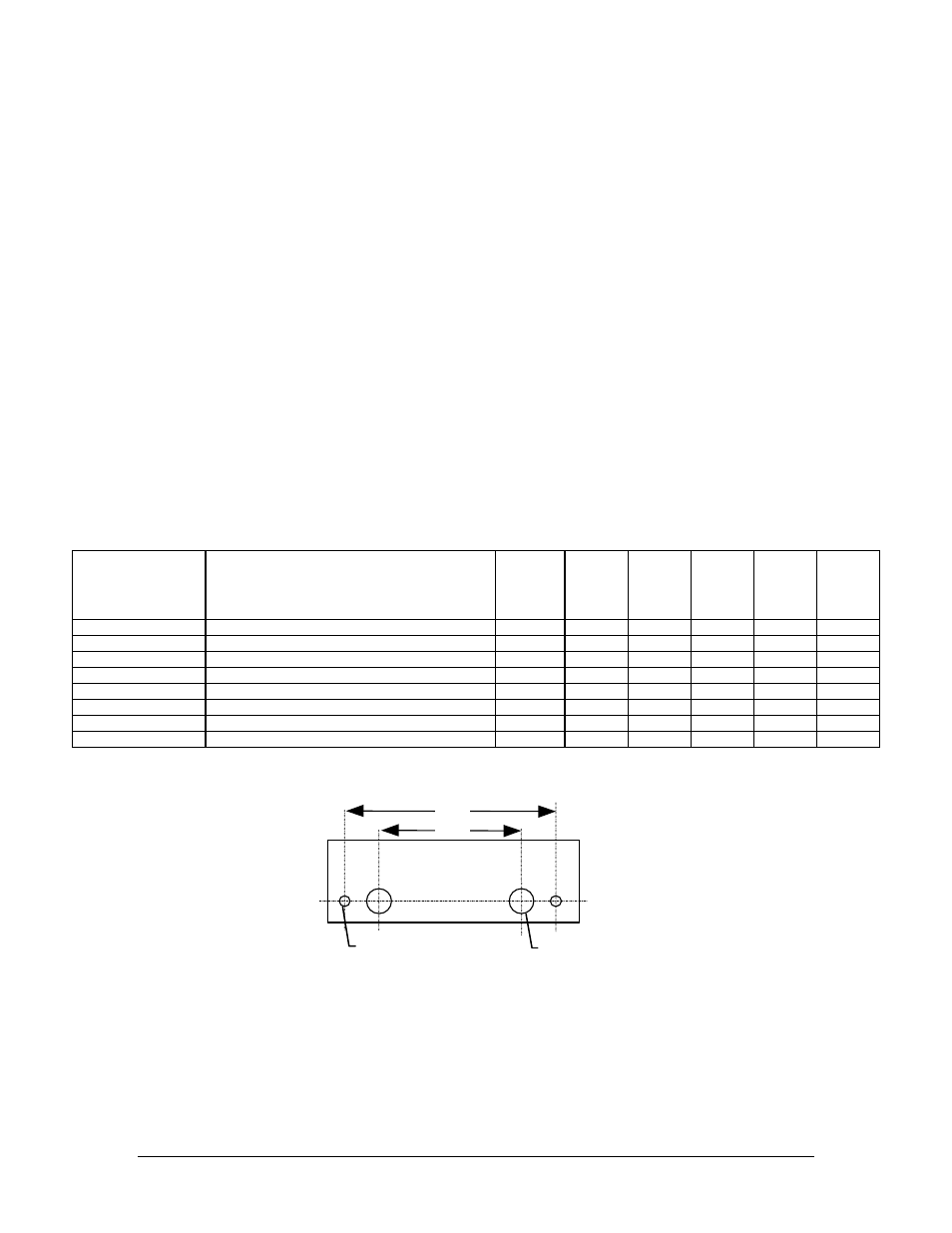
2.3
Equipment installation procedures
2 ea. 0.125
2 ea. 0.315
2.40”
1.68”
NOT TO SCALE