Electrical noise issues, Power requirements, Side tone – PS Engineering PM2000 User Manual
Page 4: Entertainment hook up, External push to talk installation, Operating instructions
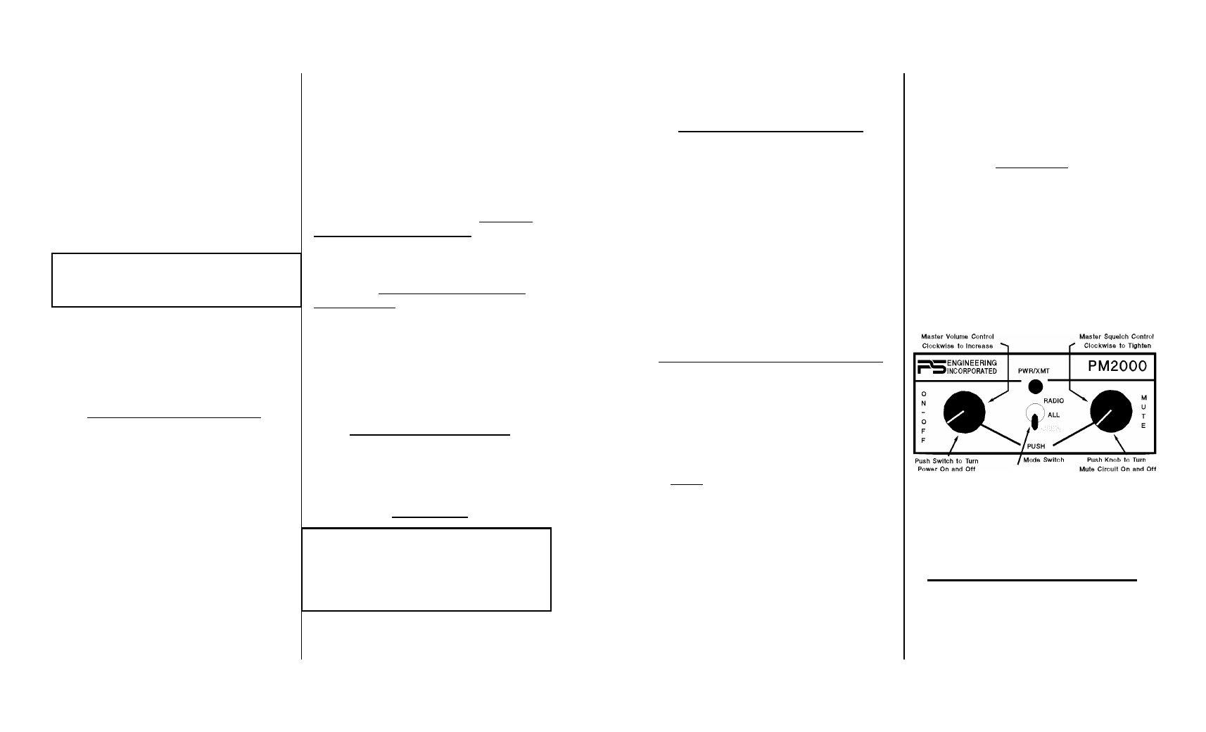
PM2000 Operation/Installation Manual
Page 4
Revision 2, August 1998
carried by the headphone wire than the micro-
phone wire. When these two wires are within the
same shielded cable, cross-coupling allows the
output to get back into the input, causing oscilla-
tions to occur.
If the aircraft already has pilot and copilot
headset jacks installed, you may re-use the hard-
ware. Remove all wires from the copilot jacks
and discard them. NOTE: You may elect to use
the existing pilot headset jacks as the auxiliary
jacks.
To hook the intercom into the system, sim-
ply parallel a set of mic and headphone wires
from this set of auxiliary jacks directly to appro-
priate points to the PM2000. Finally, install a
new set of pilot headset jacks and hook directly
to the appropriate points to the PM2000.
Electrical Noise Issues
Due to the variety of radio equipment found
in today's general aviation aircraft, there is the
potential for both radiated and conducted noise
interference. The PM2000 has a power supply
designed to reduce conducted electrical noise on
the power bus by over 50 dB. Although this is a
large amount of attenuation, it may not eliminate
all noise when the amount of noise is excessive.
In addition, there must be at least 13.8 Volts DC
present at the PM2000 for the power supply to
work in its designed regulation. Otherwise, it
will not be able to adequately attenuate all noise.
Shielding can prevent radiated noise (i.e.
beacon, electric gyros, switching power supplies)
however, installation combinations can occur
wherein minor interference is possible. The
PM2000 was designed in a RFI hardened chas-
sis and has internal bypass capacitors on all
input lines. RFI can still cause problems, like
low or distorted sidetone, if correct shielding
techniques are not observed.
Ground loop noise occurs when there are
two ground paths for the same signal, i.e. air-
frame and ground return wire. Large cyclic
loads such as strobes, inverters, etc., can inject
audible signals onto the airframe. Follow the
wiring diagram very carefully to help insure a
minimum of ground loop potential. Radiated
signals can also be a factor when low level mic
signals are "bundled" with current carrying
power wires. Keep these cables separated as
much as possible.
Mil-spec 2– and 3-conductor shielded wire
MUST be used as shown in the installation dia-
gram for proper operation.
It is very important that you use insulating
washers on all microphone and headphone
jacks to isolate the audio signal ground from
the aircraft ground.
Power Requirements
The PM2000 is designed to work with ei-
ther 12 or 28 volt DC negative ground systems.
The PM2000 must be externally fused with a 1
ampere circuit breaker.
Side Tone
If the aircraft radio does not have sidetone
(the ability to hear your voice during radio
NOTE: Auxiliary microphone and headset
jacks are required for a complete installation.
These provide troubleshooting and a back-up
access to the aircraft radios.
Note: Use the low level (or line) output from
any music device to connect to the PM2000.
Maximum input level is 1 V peak-to-peak.
DO NOT USE SPEAKER OUTPUT.
Revision 2, August 1998
Page 5
200-195-0002
transmissions) the PM2000 can be modified to
provide sidetone for you. Call the factory for de-
tails.
Entertainment Hook Up
A stereo entertainment device (CD player,
cassette player, etc.) can be connected to the
PM2000. You may want to install a " stereo
connector (provided) somewhere in the panel so
that you can easily plug in an entertainment de-
vice.
The entertainment will be automatically
muted when the ICS or aircraft radio becomes
active. The “Soft Mute™” feature slowly returns
the music to full volume when the ICS or radio
becomes quiet. The muting feature is selectable
by depressing squelch control (
PUSH
-
MUTE
switch).
External Push to Talk Installation
Part of the installation includes the installa-
tion of PTT (Push To Talk) switches that allow
the use of your aircraft communications radio for
transmissions.
There are three configurations that can be
used. You select the case that best fits your instal-
lation requirements.
NOTE: Only the person who presses their
PTT switch will be heard over the radio.
CASE I
PTT built into the pilot and copilot
yokes
Simply install the plugs from the head-
set into the aircraft headphone jacks. Use
the yoke mounted PTT to transmit. No
other action is required.
CASE II
Built-in PTT on the pilot side only,
but copilot transmit capabilities de-
sired.
This configuration requires a modified
external PTT plugged into the copilot's
mic jack. See Appendix A for modifica-
tion details. When the copilot's PTT is
depressed, this activates an intercom re-
lay that switches the mic audio input to
aircraft radio to the copilot.
CASE III
No built-in PTT switch at all
If there is no built-in PTT switch at
all, an external, properly modified PTT
switch is required. Both the pilot and
copilot may use an external PTT. (See
Appendix A.)
OPERATING INSTRUCTIONS
With the installation complete, turn the
PM2000 on by pushing in the left knob
(volume control). This also engages the auto-
matic fail-safe system.
Front Panel Controls