Specifications, Installation, Mode select – PS Engineering PM2000 User Manual
Page 3
PM2000 Operation/Installation Manual
Page 6
Revision 2, August 1998
is a delay of about a half second before the chan-
nel closes. This prevents closure between words
and eliminates choppy communications.
Mode Select
The center switch is a 2- position mode
switch that allows the pilot to tailor the intercom
function to best meet the pilot's needs. Regard-
less of configuration, the pilot will always hear
the aircraft radio.
ISO (Up Position): The pilot is isolated from
the intercom and is connected to the aircraft ra-
dios only . He will hear only the aircraft radio
reception and sidetone (only during radio trans-
missions). Copilot and passengers will hear the
intercom and music but not the aircraft radio re-
ceptions or transmissions.
All (Middle position): All parties will hear
the aircraft radio reception and transmissions,
intercom, and music. However, during any inter-
com or radio communications, the music volume
automatically decreases. The music volume in-
creases gradually back to the original level after
communications have been completed. There is a
lower switch position that is the same as ALL.
NOTE: When either the pilot or copilot PTT
is depressed, all microphones are off except for
the transmitting one.
Adjustment of Aircraft Radio Mute Level
The audio level that mutes the entertainment
when the radio is active is determined by the set-
ting of the aircraft radio mute circuit. This circuit
is adjusted at the factory for optimum sensitivity.
If the entertainment appears to be always muted
(music stays at a constant low level even when
the ICS is not being used) the mute trigger level
must be adjusted. The mute level is changed by
adjusting the small potentiometer located at the
rear of the intercom. This is a 20-turn pot ,so you
Adjusting The Volume
The volume control knob adjusts the loud-
ness of the intercom and music for all headsets.
Turning the control clockwise increases the
audio. The PM2000 has two individual output
amplifiers for each headset in the system that
provide plenty of undistorted audio output
power.
NOTE: Volume level does not change with
the number of headsets installed.
The volume control on the PM2000 does
not affect the volume level of the aircraft radio.
This gives the pilot ability to adjust the aircraft
radio and the ICS volume independently, add-
ing flexibility to the system.
Adjusting The Squelch Control
This VOX operated intercom keeps all mi-
crophone channels off while the pilot, copilot or
passengers are not speaking. This reduces back-
ground noise from the aircraft. Only when
someone speaks will their microphones auto-
matically turn on, passing the audio through the
system. Although there is just one squelch con-
trol, there are actually three distinct squelch
circuits. One each for the Pilot, Copilot, and
Passengers 1 & 2.
Set the Squelch control knob by slowly ro-
tating the squelch knob clockwise until you no
longer hear the engine noise in the earphones.
When the microphone is positioned properly
near your lips, normal speech levels should
open the channel. When you stop talking, there
NOTE: In the event of a power failure to the
PM2000, or if the power switch is turned off, the
copilot will not hear the aircraft radio. Only the
pilot is connected to the aircraft radio.
Revision 2, August 1998
Page 3
200-195-0002
all other mics are disabled. For pilot override,
the unit can be switched off.
Specifications
Input power:
12-28 Volts DC
Current Drain:
< 150 mA Externally fused at 1
Amp
Headphone Impedance:
150-
1000
Ω
Typical
Audio Distortion:
<10% @ 150mW into 150
Ω
load
Aircraft Radio Impedance:
1000
Ω
Typical
±3 dB Mic Frequency Response: 350 Hz-6000 Hz
±3 dB Music Frequency Response:
200 Hz - 15
kHz
Net weight:
12 Ounces (.340 kg)
Dimensions:
1.25" H X 3.00" W X 5.50" D
(3.2 cm x 7.7 cm x 14 cm)
Installation
The PM2000 was carefully inspected me-
chanically and thoroughly tested electrically
before shipment. It should be free electrical or
cosmetic defects. Upon receipt, verify that the
parts kit contains the following:
A. Two # 4-40 Black machine screws
B. One reversible face plate
C. Two black knobs with white lines
D. One 25 pin Sub-D female connector
with hood
C. Two connector thumbscrews
D. One hole placement template
E. One stereo/mono switch for pilot head-
set.
F. Four complete sets of jacks with insu-
lating washers and 1/8” music jack
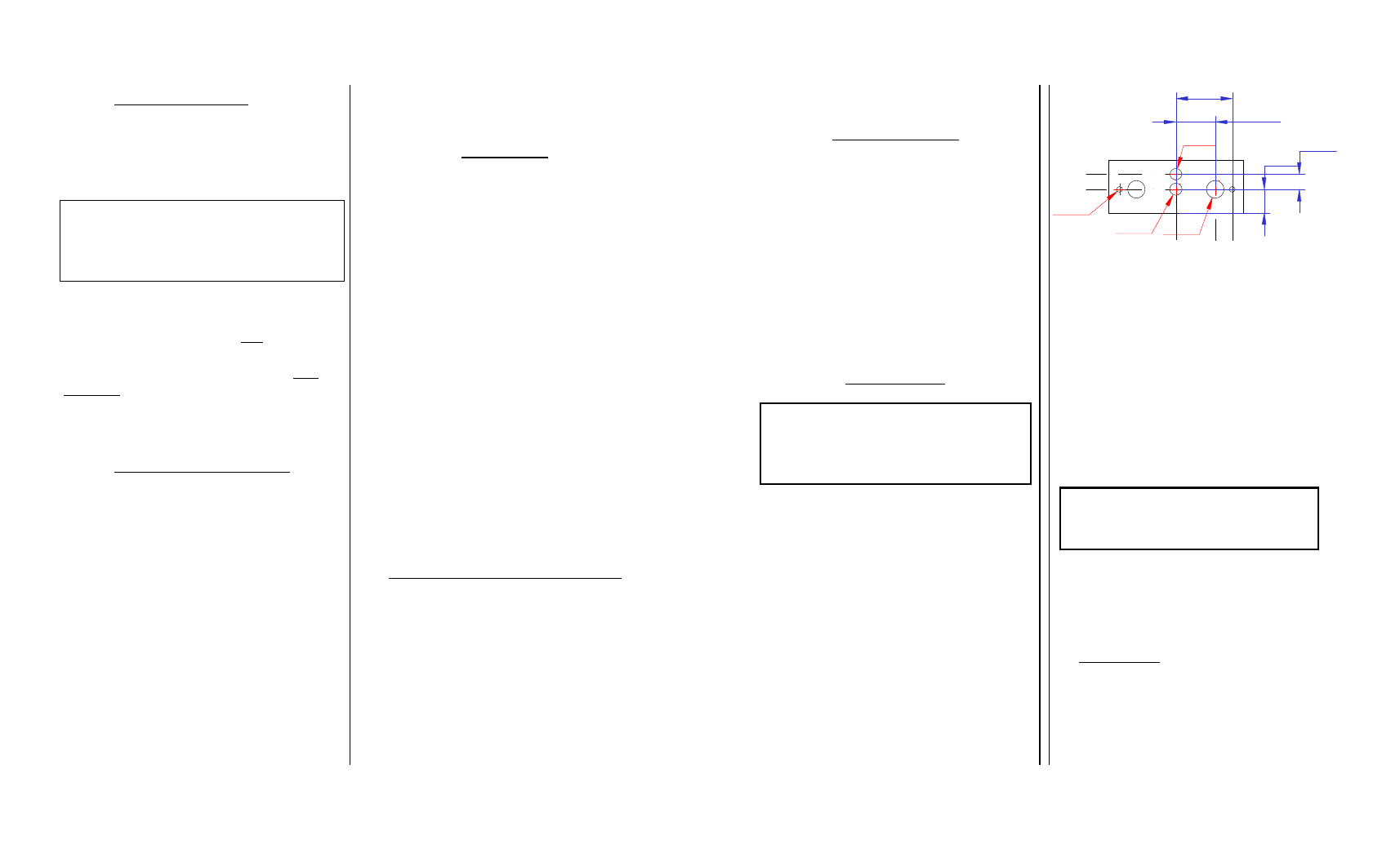
1. Drill six holes as indicated in a location
convenient to the pilot position(s).
2. Once the holes have been drilled, insert
the PM2000 from behind the instrument panel
through the four holes for the knobs, LED, and
switch.
3. Place the aluminum face plate over the
knob shafts, and secure with the two black #4-40
screws provided.
4. Next install the two knobs by pressing
them on the shafts.
5. To complete the installation, a wire har-
ness must be made and routed as depicted at the
back of the manual.
IMPORTANT: You must use separate
shielded cable for the microphone and head-
phone jacks. Combining these two wires WILL
cause loud oscillations and degrade the intercom
functions. The cause of the oscillation is due to
the fact that there is a much larger signal being
Note: Approval basis for installing a
PM2000 in certified aircraft is the
responsibility of the installer.
NOTE: A custom wire harness can be cus-
tom made to your specifications by the
factory. Call the factory for more details.
Ø0.125 in
Ø0.265 in
Ø0.375 in
Ø0.25 in
0.838 in
1.2 in
0.5 in
0.32 in
Hole placement diagram