1 electrical noise issues, 2 power requirements, 5 post installation checkout – PS Engineering PM1000DAP User Manual
Page 4: Environmental qualification form
PM1000-DAP Dual Audio System Intercom
Page 4
April 2008
2.4.1 Electrical Noise Issues
WARNING: You must use separate shielded
cables for the microphone and headphone con-
nections to the PM1000-DAP. Combining these
two wires WILL cause loud oscillations and de-
grade the intercom function. The oscillation is
caused by the cross-coupling between the large
headphone signal and the small microphone sig-
nal. The resulting feedback is a high-pitched
squeal that varies with the volume controls.
Due to the variety of the radio equipment
found in today's general aviation aircraft, there
is the potential of both radiated and conducted
noise interference. The PM1000-DAP has a spe-
cially designed power supply to reduce con-
ducted electrical noise on the power bus of the
aircraft by at least 50dB. Although this is a very
large amount of attenuation, it does not elimi-
nate all noise when the amount is excessive.
There must be at least 12 Volts DC present at
the PM1000-DAP for the power supply to work
within its designed regulation. Otherwise, it will
not be able to attenuate noise properly.
Shielding can protect the system from radi-
ated noise (rotating beacon, electric gyros,
switching power supplies, etc.). However, instal-
lation combinations can occur where minor inter-
ference is possible. The PM1000-DAP was de-
signed in an interference -protected chassis and
has internal filter capacitors on all input lines.
Ground loop noise occurs when there are
two different return paths for the same signal,
such as airframe and ground return wire. Large
cyclic loads such as strobes, inverters, etc., can
inject audible signals onto the airframe return
path. Follow the wiring diagram very carefully to
help insure a minimum of ground loop potential.
Radiated signals can be a factor when low level
mic signals are bundled with current carrying
power wires. Keep these cables separated.
.
2.4.2 Power
Requirements
The PM1000-DAP was designed to work
with either 12/28 volt DC negative ground sys-
tems. The PM1000-DAP must be externally
protected with a one ampere (1A) circuit
breaker or fuse.
2.5
Post installation checkout
After wiring is complete, verify power is
ONLY on pin 14 of the connector, and airframe
ground on pin 1. Failure to do so will cause
internal damage and void PS Engineering's war-
ranty.
1. Apply power to the aircraft and avionics.
2. Plug headsets into the pilot and copilot
positions.
3. Verify that both pilot positions can trans-
mit and receive with the PM1000-DAP in
1
2
3
4
5
14
15
16
17
18
6
7
8
9
19
20
21
22
10
23
24
11
12
25
13
P
o
w
e
r (
1
1
-3
3
V
D
C
)
G
ro
u
n
d
P
ilo
t P
h
o
n
e
s
G
n
d
P
ilo
t P
h
o
n
e
s
H
i
C
o
p
ilo
t P
h
o
n
e
s
L
o
C
o
p
ilo
t P
h
o
n
e
s
H
i
C
o
p
ilo
t M
ic
H
i
C
o
p
ilo
t P
T
T
C
o
p
ilo
t &
P
a
s
s
M
ic
L
o
P
ilo
t M
ic
A
u
d
io
H
i
P
ilo
t M
ic
L
o
N
o
C
o
n
n
e
c
tio
n
N
o
C
o
n
n
e
c
tio
n
N
o
C
o
n
n
e
c
tio
n
N
o
C
o
n
n
e
c
tio
n
N
o
C
o
n
n
e
c
tio
n
N
o
C
o
n
n
e
c
tio
n
N
o
C
o
n
n
e
c
tio
n
N
o
C
o
n
n
e
c
tio
n
N
o
C
o
n
n
e
c
tio
n
N
o
C
o
n
n
e
c
tio
n
N
o
C
o
n
n
e
c
tio
n
N
o
C
o
n
n
e
c
tio
n
N
o
C
o
n
n
e
c
tio
n
N
o
C
o
n
n
e
c
tio
n
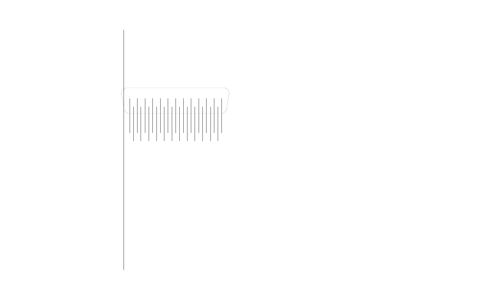
11900D Connector layout, viewed from rear
Revision 5
Page 9
200-191-0000
Environmental Qualification Form
Nomenclature: Aircraft Audio Selector Panel and Amplifiers
Model Number: PM1000
FAA TSO Number: C50c
Manufacturer’s Specification:
Technical qualifications:
RTCA/DO-170 Class II
PS Engineering Incorporated
9800 Martel Road Lenoir City TN 37772 Telephone (865) 988-980
Conditions
Section
Conducted Tests
Temperature and Altitude
Low Temperature
High Short Time Temp
High operating Temp
Altitude
4.0
4.5.1
4.5.2
4.5.4
4.6.1
Equipment tested to CAT A1
Temperature variation
5.0
Equipment tested to Category C
Humidity
Standard Humidity Environment
6.0
6.3.1
Equipment tested to Category A
Operational Shocks/Safety
7.0
7.2.1
Equipment tested to DO-160B, no cate-
gory
Vibration
Standard Vibration Test
Sinusoidal Test
Critical Frequency Survey
8.0
8.3
8.3.1
8.3.2.1
Equipment tested to DO-160B, Category
S
Explosion Proofness
9.0
Category X, not tested
Waterproofness
10.0
Category X, not tested
Fluids Susceptibility
11.0
Category X, not tested
Sand and Dust
12.0
Category X, not tested
Fungus
13.0
Category X, not tested
Salt Spray
14.0
Category X, not tested
Magnetic Effect Test
15.0
Equipment tested to Category X
Power input
16.0
Equipment tested to Category B
Voltage Spike
17.0
Equipment tested to Category B
Audio Frequency Susceptibility
18.0
Equipment tested to Category B
Induced Frequency Susceptibility
19.0
Equipment tested to Category B
Radio Frequency Susceptibility
20.0
Equipment tested to Category T
Radio Frequency Emission
21.0
Equipment tested to Category B
Lightning Induced Transient Suscepti-
bility
22.0
Category X, not tested