1 introduction, 2 scope, 3 description – PS Engineering PM1000 (11909) User Manual
Page 2: Aux mic jack, Aux headphone jack
PM1000II Specialty Intercom Manual
Page 2
Sept. 2007
Section I General Information
1.1 Introduction
The PM1000II, is a panel mounted, 4-place
monaural intercom system (ICS). Please read
this manual completely before installation to
minimize the risk of damage to the unit and to
become familiar with all the features.
1.2 Scope
This manual contains installation and
operational instructions for the following PS
Engineering unit:
Part Number
Description
11909
Push to talk intercom for use in noisy cockpits
1.3 Description
The PM1000II is a 4-place, panel mounted
intercom with individual volume and squelch
controls for the pilot and copilot. The copilot's
squelch control adjusts the trip level of the
copilot and passengers.
A front panel mode switch allows the pilot
to select two intercom configurations:
"ISO" mode isolates the pilot from the
intercom and connects to the aircraft radio. The
passengers can continue to communicate with
each other and listen to entertainment without
distracting the pilot. They do not hear radio
communications.
"ALL" mode places all headsets on a party
line. Each one hears aircraft radio, entertainment
and can use the intercom.
The PM1000II has an automatic fail-safe
interconnect to the aircraft radio. If power to the
intercom is disrupted, an internal relay will
connect the pilot's headset to the aircraft radio.
This allows continuous radio communications.
Note: The copilot will no longer hear aircraft
radio when power is removed.
The 2-color LED shows green when power is
on and red during radio transmissions. This
functions as a stuck mic indicator.
An auxiliary input is provided, allowing the
pilot, copilot and passengers the option to listen
to music during flight. During intercom or aircraft
radio activity, this music is automatically muted
to allow communications without distraction.
When the activity ceases, the Soft Mute circuit
will gradually return the music to the original
listening volume.
The "ISO" mode provides uninterrupted
aircraft radio communications for the Pilot.
Because the pilot's intercom volume control does
not affect the aircraft radio volume, it is possible
to select various balances of volume level
between the ICS and the aircraft radio while in
the ALL mode. Reducing the intercom volume,
the pilot places the aircraft radio in the
foreground while the ICS is in the background.
Both pilot and copilot have transmit
capabilities over the radio. The PM1000II allows
only the person who presses their PTT to be heard
over the aircraft radio. If both pilot and copilot
press the PTT at the same time, the copilot will
override (Ideally suited for training
environments). Pilot regains priority by switching
PM1000II, p/n 11909, Front Panel
Sept. 2007
Page 9
200-125-0100
PS Engineering, Inc. 2002©
Copyright Notice
Any reproduction or retransmittal of this publication, or any portion thereof, without the expressed written permission of PS Engineering, Inc. is strictly
prohibited. For further information contact the Publications Manager at PS Engineering, Inc., 9800 Martel Road, Lenoir City, TN 37772. Phone (865) 988-
9800
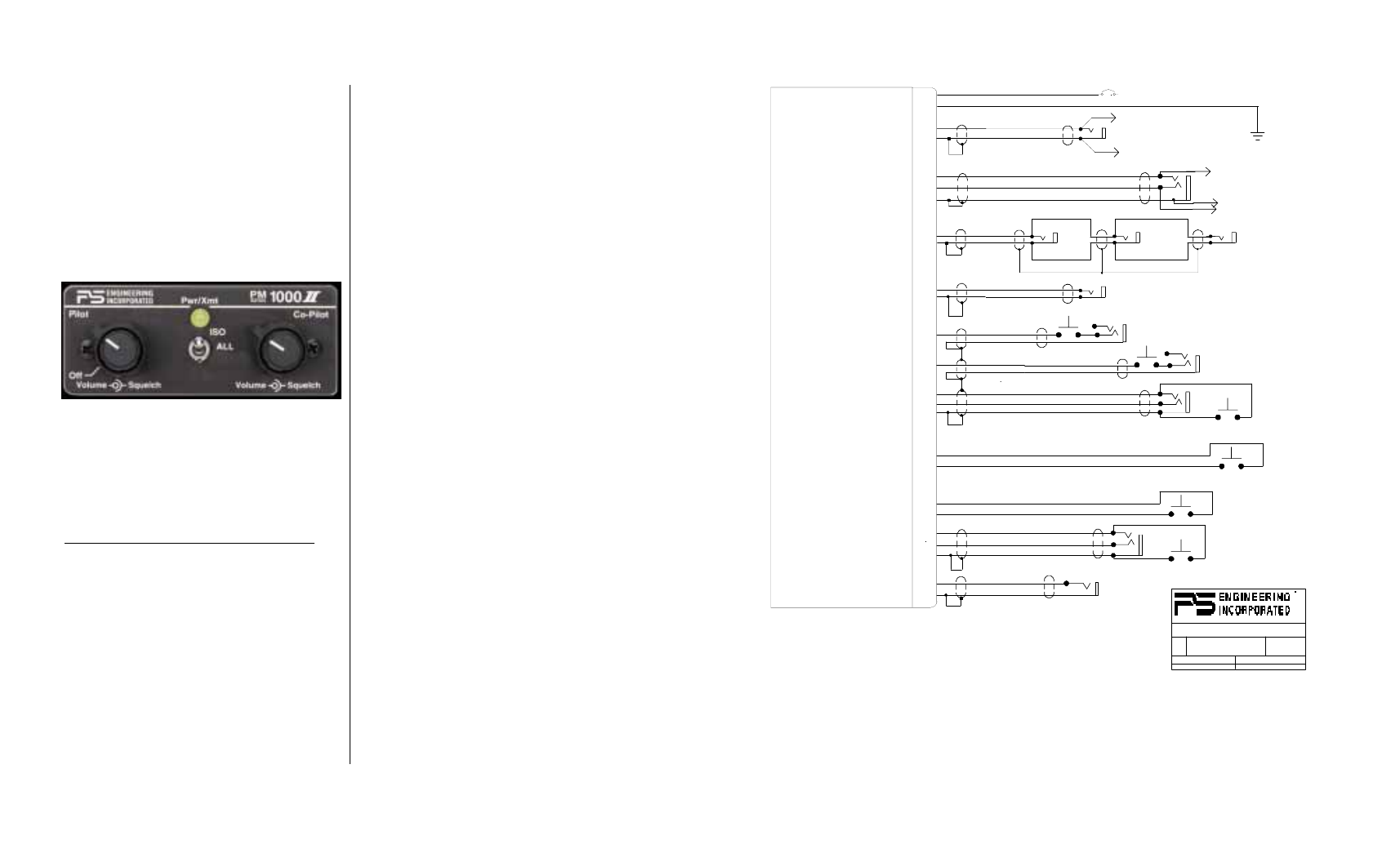
PM1000II
with PTT-ICS, p/n 11909
1A
11-33 VDC
14
1
To Aircraft Radio
Phone Hi
17
4
Power In
Ground
A/C Radio Phone Audio Hi
A/C Radio Phone Audio Lo
18
5
Pilot Phone Audio Hi
Pilot Phone Audio Lo
Copilot
Phones
Passenger 1
Phones
Passenger 2
Phones
Copilot, Pax 1 & 2 Phones Hi
Copilot, Pax 1 & 2 Phones Lo
19
6
20
7
9
Music Jack
Pass 1 Mic
Pass 2 Mic
22
21
10
Music Input Hi
Music Input Lo
Pass 1 Mic Audio Hi
Pass 1 Mic Audio Lo
Copilot Mic PTT
Copilot Mic Audio Hi
Mic Audio Lo
Copilot PTT
Pilot Mic PTT
Pilot Mic Audio Hi
Pilot Mic Audio Lo
Aux Mic Jack
Pilot PTT
To A/C Radio Mic Audio Hi
Aircraft Radio PTT
12
25
13
24
23
11
8
Pass 2 Mic Audio Hi
Pass 2 Mic Audio Lo
To Aircraft Radio
Phone Low
AUX Headphone Jack
To Aircraft Radio Mic Audio Lo
Pilot Headphone Jack
NOTES:1. All wire must conform to MIL-22759
or 27500. Minumum 24 gage shielded wire.
2. Use 2- and 3-conductor with shield as indicated.
3. Use insulating washers on all jacks.
4. Connect shields at intercom end only
5. AUX headphone and microphone jacks are required.
6. If a VOX operation is desired, a SPST switch can be
wired across the PTT momentary switches, or a mom-0ff-0n toggle switch..
Copilot Mic Jack
Pilot Mic Jack
Aircraft Radio PTT
Aircraft Mic Audio Hi
Aircraft Mic Audio Lo
REV
DATE:
ECO
SHEET OF
TITLE:
DOCUMENT NUMBER:
SIZE
PM1000II w/PTT-ICS (11909) WIRING
120-129-0000
1
08/11/98
1
1
9800 MARTEL ROAD, LENOIR CITY TN 37772
3
16
Pilot ICS PTT
Pilot ICS PTT
2
15
Copilot ICS PTT
Copilot ICS PTT
Copilot ICS PTT
Pilot ICS PTT
Pass ICS PTT
Pass ICS PTT