Viewed from front of unit, Aux mic jack, Aux headphone jack – PS Engineering PM1000 User Manual
Page 7: Appendix d wiring diagrams
PS Engineering Incorporated
PM 1000 FAA TSO Approved Intercom
Installation and Operation Manual
200-190-0002
13
Rev. 2, Jan. 2001
7. Appendix C, Instructions for continuing airworthiness
The PM1000 is considered an “on-condition” maintenance item. It is checked prior to each flight during
normal operation. There are no additional considerations for continuing airworthiness other than the practices
detailed in AC 43.13-1A, Chapter 15, Paragraph 750. This includes inspecting the unit to be sure it is
securely fastened in its location, and that the wiring harness is not chafed or pinched, and remains secure. All
panel jacks should be checked at each periodic inspection to ensure that they are tight and not in contact with
other items behind the instrument panel.
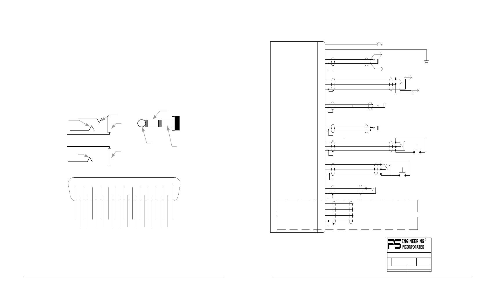
8. Appendix D Wiring Diagrams
Jack Details:
Microphone
TIP (PTT)
Ring (audio)
Barrel
(gnd)
TIP
(phone audio hi)
Barrel
(audio gnd)
headphone
Headset Plug
TIP (PTT)
Ring (audio)
Barrel (gnd)
(audio)
1 2
3
4 5
14 15 16 17 18
6
7 8
9
19 20 21 22
10
23 24
11 12
25
13
Pass Phones Hi
Pass Phones Lo
Power (11-33 VDC)
Ground
Music 2 Hi
Music #2 Lo
A/C Radio Ground
A/C Radio Input
Pilot Phones Gnd
Pilot Phones Hi
Copilot Phones Lo
Copilot Phones Hi
Music 1 Input Lo
Music 1 Input Hi
No Connection
Copilot Mic Hi
No Connection
Copilot PTT
Copilot & Pass Mic Lo
Pilot Mic Audio Hi
Pilot Mic Lo
Pilot PTT
A/C Radio PTT
A/C Mic Audio Hi
A/C Radio Gnd
Viewed from Front of Unit
Figure 2 Connector Diagram (Unit has Male Pins)
PS Engineering Incorporated
PM 1000 FAA TSO Approved Intercom
Installation and Operation Manual
200-190-0002
14
Rev. 2, Jan. 2001
1A
11-33 VDC
14
1
11900 Sub-D DB-25 Male (on unit)
To Aircraft Radio
Phone Hi
17
4
Power In
Ground
A/C Radio Phone Audio Hi
A/C Radio Phone Audio Lo
18
5
Pilot Phone Audio Hi
Pilot Phone Audio Lo
Copilot Phones Audio Hi
Copilot Phones Audio Lo
19
6
20
7
Music Jack
22
21
10
Music Input Hi
Music Input Lo
Copilot Mic PTT
Copilot Mic Audio Hi
Mic Audio Lo
Copilot PTT
Pilot Mic PTT
Pilot Mic Audio Hi
Pilot Mic Audio Lo
Aux Mic Jack
Pilot PTT
To A/C Radio Mic Audio Hi
Aircraft Radio PTT
12
25
13
15
3
16
2
Power Out (+9VDC)
Expansion Audio In
Expansion Audio Out
Ground
To Pin 3 of 11918 expansion module
To Pin 1 of 11918
To Pin 4 of 11918
To Pin 2 of 11918
24
23
11
To Aircraft Radio
Phone Low
AUX Headphone Jack
To Aircraft Radio Mic Audio Lo
Pilot Headphone Jack
These pins used for expansion modules only
NOTES:
1. All wire must conform to MIL-22759
or 27500. Minumum 24 gage shielded wire.
2. Use 2-, 3-, and 4-conductor with shield
as indicated.
3. Use insulating washers on all jacks.
4. Connect shields at intercom end only
5. AUX headphone and microphone jacks are
required.
Copilot Mic Jack
Pilot Mic Jack
Aircraft Radio PTT
Aircraft Mic Audio Hi
Aircraft Mic Audio Lo
REV
DATE:
ECO
SHEET OF
TITLE:
DOCUMENT NUMBER:
SIZE
PM1000 (11900) 2-PLACE WIRING DIAGRAM
120-121-0001
2
11/06/98
1
1
9800 MARTEL ROAD, LENOIR CITY TN 37922
Copilot Headphone Jack
8
9
No Connection
No Connection